| OPERATING PROCEDURE | PHOTOS | |
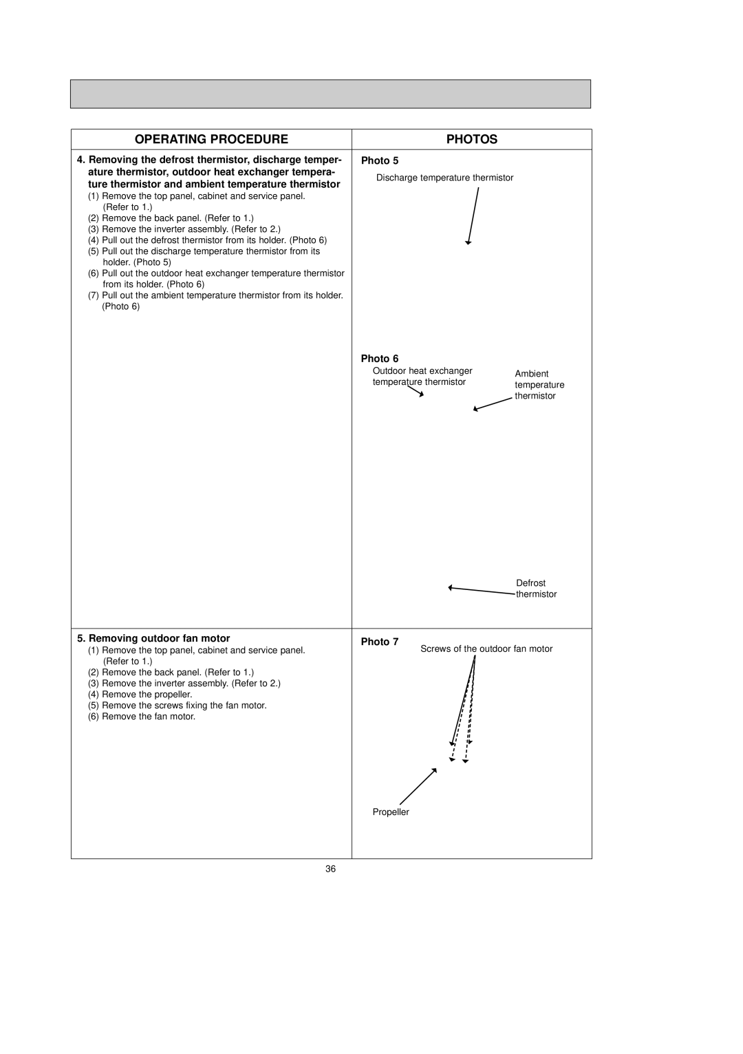
4. Removing the defrost thermistor, discharge temper- | Photo 5 | ||
ature thermistor, outdoor heat exchanger tempera- | Discharge temperature thermistor | ||
ture thermistor and ambient temperature thermistor | |||
| |||
(1) | Remove the top panel, cabinet and service panel. |
| |
| (Refer to 1.) |
| |
(2) | Remove the back panel. (Refer to 1.) |
| |
(3) | Remove the inverter assembly. (Refer to 2.) |
| |
(4) | Pull out the defrost thermistor from its holder. (Photo 6) |
| |
(5)Pull out the discharge temperature thermistor from its holder. (Photo 5)
(6)Pull out the outdoor heat exchanger temperature thermistor from its holder. (Photo 6)
(7)Pull out the ambient temperature thermistor from its holder. (Photo 6)
Photo 6
Outdoor heat exchanger | Ambient | |
temperature thermistor | ||
temperature | ||
| ||
| thermistor |
| Defrost | |
| thermistor | |
|
| |
5. Removing outdoor fan motor | Photo 7 | |
(1) Remove the top panel, cabinet and service panel. | ||
Screws of the outdoor fan motor | ||
(Refer to 1.) |
|
(2)Remove the back panel. (Refer to 1.)
(3)Remove the inverter assembly. (Refer to 2.)
(4)Remove the propeller.
(5)Remove the screws fixing the fan motor.
(6)Remove the fan motor.
Propeller
36