Data Book
Contents
Safety for USE
For correct installation
Do not wash the unit with water
Indoor unit
Complete Line UP
Outdoor unit
Features
Descriptions
Mechanical Specifications
Typical Installation Example
MODEL-DESIGNATION Breakdown
10 M Y C
Specifications
PE-7~20MYC Cooling only
PEH-5,7,8MYA Heat pump
PEH-10,15,20MYA Heat pump
Electrical Data
PE-7~20MYC-EU
PEH-5,7,8MYA-EU
Heating
PEH-10,15,20MYA-EU
Selection Procedure
Model Selection With actual examples
Efficiency Calculation
Calculation of net capacity
Cooling Capacity Standard Air Flow
Capacity Tables
Factor for Various Air Flow
Heating Capacity Standard Air Flow
PE-7MYC-EU , PEH-7MYA-EU
PEH-7MYA-EU
PE-8MYC-EU , PEH-8MYA-EU combined with PUH-8MYC1-EU
PEH-8MYA-EU
Use for low ambient cooling parts
PE-8MYC-EU , PEH-8MYA-EU combined with PUH-8MYE-EU
PE-8MYC-EU , PEH-8MYA-EU combined with PUH-8ME-EU
Combined with PUH-8MYE-EU
PE-10MYC-EU , PEH-10MYA-EU combined with PUH-10MYC1-EU
PEH-10MYA-EU
PE-10MYC-EU , PEH-10MYA-EU combined with PUH-10MYE-EU
Combined with PUH-10MYE-EU
PE-15MYC-EU
976
PEH-15MYA-EU
989 011
PE-20MYC-EU
Use for low ambient cooling parts
PEH-20MYA-EU
PEH-20MYC-EU AIR Volume CMM
Operation Range
Cooling
FAN Performance
PEH-5MYA-EU
PE-7MYC-EU PEH-7MYA-EU
PE-8MYC-EU PE-10MYC-EU PEH-8MYA-EU PEH-10MYA-EU
PE-15MYC-EU PEH-15MYA-EU
PE-20MYC-EU PEH-20MYA-EU
Pulley outside dimensions are shown below Unit mm
Sound Data
Position mesurement
Indoor units
Outdoor units
PEH-5
Outline Dimensions
PEH-7,8
PEH-10
PEH-15
28.6
DRAINRc HOLES26
PEH-20
Flange HOLES28
PUH-5
PUH-7,8,10 Upper blow
Holes
Holes 2-ø15 Ø19.053/4
PUH-8,10 Side blow
PU-15
Ø15.885/8130 Refrigerant Pipe PUH-8ø25.41 PUH-10ø28.61-1/8
Cable Entry 44 Holes 2-ø15
PU-20
PUH-15,20
Ø28.61-1/8 Ø15.885/8
Holes 6-ø15 Control Cable Entry ø27
Duct work is local supply
Wiring Diagrams
PE-7MYC-EU Standard
Internal thermostat indoor fan
PE-8,10MYC-EU Standard
Over current relayfanI/D,O/D
PE-15MYC-EU Standard
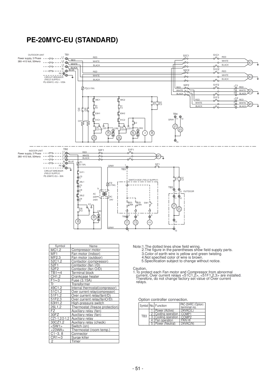
PE-20MYC-EU Standard
TB1
PE-7MYC-EU Special Order Anti Short Cycle Timer
PE-8,10MYC-EU Special Order Anti Short Cycle Timer
Internal thermostatindoor fan
PE-15MYC-EU Special Order Anti Short Cycle Timer
PE-20MYC-EU Special Order Anti Short Cycle Timer
Symbol Name MC1,2 Compressor motor
23C Ambient temperature
PE-7MYC-EU Special Order LOW Ambient Cooling
52F1 Contactor fan I/D
49F Internal thermostatfan O/D
PE-8,10MYC-EU Special Order LOW Ambient Cooling
PE-15MYC-EU Special Order LOW Ambient Cooling
Do not change factory set value of Over current relays
Auxiliary relay fanI/D
PE-20MYC-EU Special Order LOW Ambient Cooling
30FZ Auxiliary relay fanI/D
PEH-5MYA-EU Standard
MF2
PEH-7MYA-EU Standard
Thermostat defrost
Way valve
Option controller connection
C1~7
PEH-8,10MYA-EU Standard
CR1 Surge killer
PEH-15,20MYA-EU Standard
MF2
Cool Heat
CR1 Surge killer Timer Anti short cycle
PEH-8,10MYA-EU
PEH-15,20MYA-EU Special Wiring Anti Short Cycle Timer
PEH-7MYA-EU Special Order LOW Ambient Cooling
PEH-8,10MYA-EU Special Order LOW Ambient Cooling
MF2 Fan motor outdoor
52F1 Contactor fan I/D 52F2 Contactor fan O/D 52F4
CR1 Surge killer 21S4 Way valve 26D1 Thermostat defrost 26L
PEH-15,20MYA-EU Special Order LOW Ambient Cooling
63H1,2 High-pressure switch 26L1,2
51F1~5
PE-7,8,10MYC-EU
Electrical Operation Flow Charts
PEH-5MYA-EU, PEH-7,8,10MYA-EU
PE-15MYC-EU PE-20MYC-EU
PEH-15,20MYA-EU
PE-7,8,10,15,20MYC-EU
Refrigerant Schematics
PEH-5,7,8,10,15,20MYA-EU
Safety & Control Devices
PE-7,8,10MYC-EU PE-15,20MYC-EU
PEH-7,8,10MYA-EU
Special Order
Service ref
Year
Physical Data
PE-7,8,1015,20MYC-EU
Indoor AIR Circuit
Enclosure and Frame
PEH Series
PEH-5MYA-EU
PE-8MYA-EU
JH527YE JH521YE
596X1415
PUH-10MYC1-EU PUH-10MYE-EU PUH-15MYC1-EU PUH-20MYC1-EU
Space required around unit Indoor unit
Installation
Outdoor unit
Ceiling Over
Service-panel
Over 500
PU-15 At a single installation
Over Service Panel
Over Service-panel
Preparation before installing Indoor unit
Over Service-panel 500
Installation of the unit Indoor unit
Outdoor unit
Nut Washer
Nut M10 Washer
Duct construction
Lifting method
Piping connection
Case of Brazing type
Valve knob
Pipe assy
Throw away Fig By-pass tube Flange assy Extension pipe
Extension pipe Use the attached new packing Fig
Good example Bad example
Evacuation
Airtight test
Additional refrigerant charge
Drain piping
Arrangement such as terminal block in control box
Electric wiring
Control module of outdoor unit PUH-5, 8
Terminal block for connection wires
Power supply wires
Control module of outdoor unit PUH-7, 8
Control module of outdoor unit PU-20
Method for connecting electric wire
Protection switch
50A
60A
Selection of other capacities should be
Before starting the Trial run
Putting condition of the belt
=4.5mm Flexion loadW 1.4 2.2kg
Instructions for USE
Check points for operation
Outlet grille
Ceiling Ceiling Obstacle blocking air outlet
Maintenance
Fingermarks Neutral Grease
Adhesive Isopropyl
Paste Alcohol
When beginning to use air conditioner again
When the air conditioner is not to be used for a long time
Transfer of installation
Transferring work, and construction
Place for installation
Maintenance and inspection
Regarding electric work
Conseration of the noise
Trouble shooting
At cooling, water which places to cooling piping
HOW to Operate Option PAC-204RC
Display section
Before starting operation
On / OFF Start an operation
Selecting operation When selecting operation
Room temperature adjustment To change room temperature
For fan
For cooling
Time setting
Days timer key
Timer Hold/Resume key
Clock key
Trouble shooting
Error Display
Specification Guidelines
Outdoor Unit
Memo
Mitsubishi Electric Corporation
Data Book PE,PEH