MODELS:
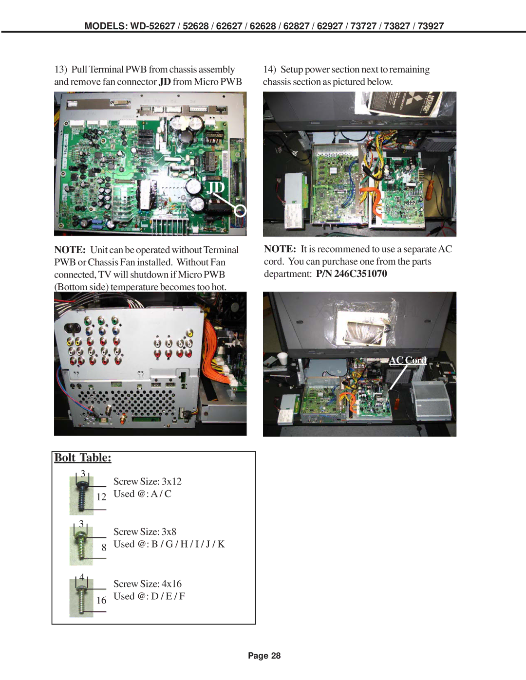
13)Pull Terminal PWB from chassis assembly and remove fan connector JD from Micro PWB
14)Setup power section next to remaining chassis section as pictured below.
JD
NOTE: Unit can be operated without Terminal PWB or Chassis Fan installed. Without Fan connected, TV will shutdown if Micro PWB (Bottom side) temperature becomes too hot.
NOTE: It is recommened to use a separate AC cord. You can purchase one from the parts department: P/N 246C351070
AC Cord
Bolt Table: |
|
3 | Screw Size: 3x12 |
|
12 | Used @: A / C | ||
|
|
|
|
3 |
| Screw Size: 3x8 | |
| |||
|
|
| |
|
|
| |
8 | Used @: B / G / H / I / J / K | ||
|
|
|
|
4
Screw Size: 4x16
16 Used @: D / E / F
Page 28