MODELS:
Optical Engine Adjustments
Test Signal Activation
1)Press “MENU-2-4-5-7” (Service Mode)
2)Press “REW” (Test Pattern).
Red = 4% overscan
White = 5% overscan
Green = 6% overscan
Cyan = 7% overscan
Yellow = 10% overscan
Required Tools
•4mm Hex Wrench (10 inches long minimum )
•5mm Allen Wrench ( 10 inches long minimum)
•10mm Hex or Phillips driver.
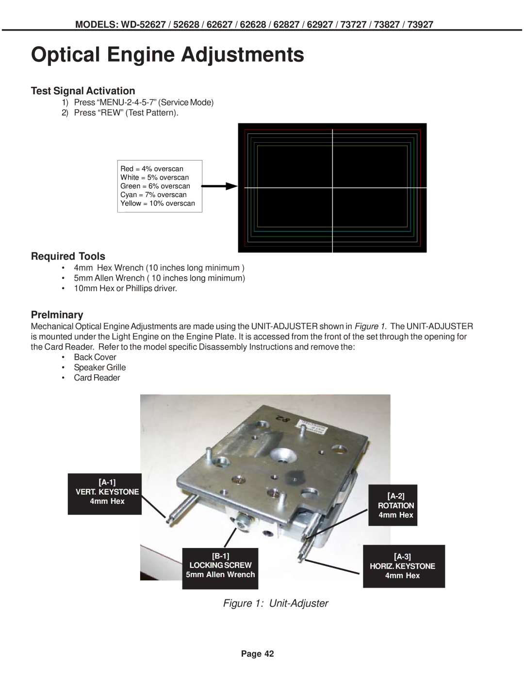
Prelminary
Mechanical Optical Engine Adjustments are made using the
•Back Cover
•Speaker Grille
•Card Reader
|
|
|
|
|
| |
VERT. KEYSTONE |
|
|
|
|
| |
4mm Hex |
|
|
|
|
| |
|
|
|
| ROTATION |
| |
|
|
|
|
|
| |
|
|
|
|
| 4mm Hex |
|
|
|
|
|
|
| |
|
|
|
|
|
|
|
|
|
|
|
|
|
|
|
|
|
| |||
|
|
|
| |||
|
| LOCKING SCREW |
|
| HORIZ. KEYSTONE | |
|
| 5mm Allen Wrench |
|
| 4mm Hex | |
|
|
|
|
|
|
|
|
|
|
|
|
|
|
Figure 1: Unit-Adjuster
Page 42