MODELS:
OPERATING CHASSIS OUTSIDE OF CABINET
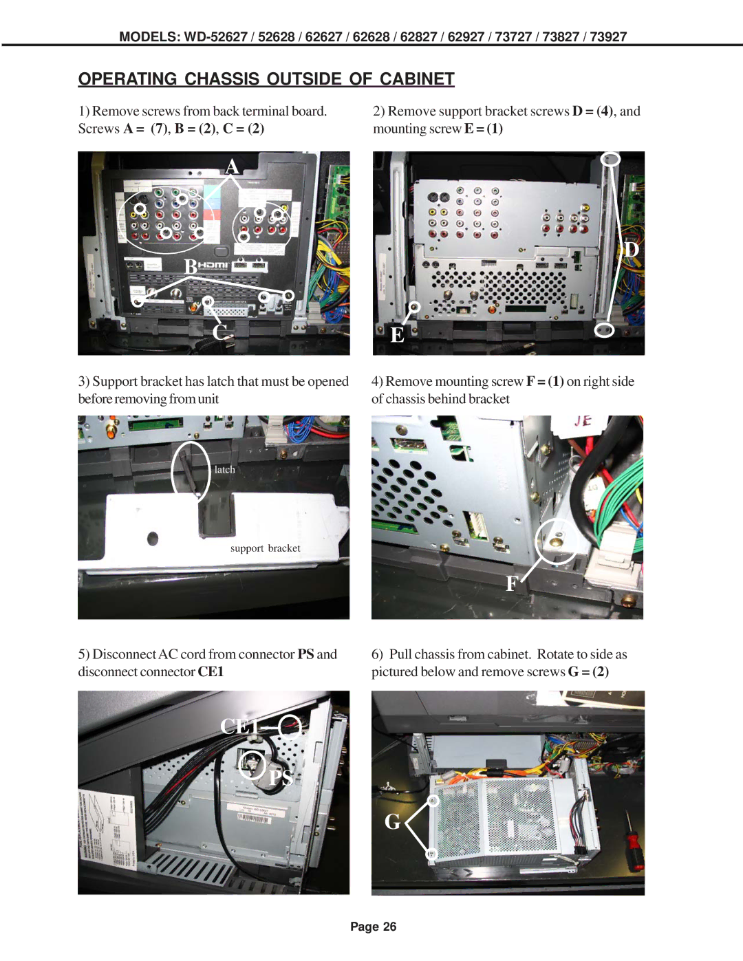
1)Remove screws from back terminal board. Screws A = (7), B = (2), C = (2)
2)Remove support bracket screws D = (4), and mounting screw E = (1)
A
B
C
3)Support bracket has latch that must be opened before removing from unit
D
E
4)Remove mounting screw F = (1) on right side of chassis behind bracket
latch
support bracket
F![]()
5)Disconnect AC cord from connector PS and disconnect connector CE1
6)Pull chassis from cabinet. Rotate to side as pictured below and remove screws G = (2)
CE1
PS
G![]()
Page 26
