Mitsubishi Electronics V29, V31 CHASSIS, V30+ specifications Locking Screws and Wedge Removal

Models: V30+ V31 CHASSIS V29 V30

1 76
Download 76 pages 15.11 Kb
Page 43
Image 43

MODELS: WD-52627 / 52628 / 62627 / 62628 / 62827 / 62927 / 73727 / 73827 / 73927

Locking Screws and Wedge Removal

Before mechanical adjustments can be made, locking screw [B-1] and [B-2] must be loosened.

[B-1] is located on the front of the UNIT-ADJUSTER. (Figure 1)

[B-2] is accessible from the rear of the unit on the right side of the Optical Engine (from the rear). (Figure 2)

Remove the rubber wedge shown in Figure 3. (52 inch and 62 inch models Only)

WARNING: DO NOT loosen [B-2] too far. The nut on the other side may drop off. Then the Optical Engine must be removed to re-install the nut.

[B-2]

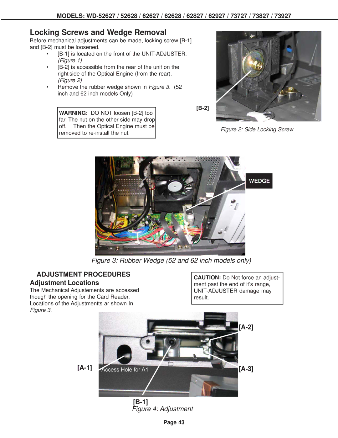
Figure 2: Side Locking Screw

WEDGE

Figure 3: Rubber Wedge (52 and 62 inch models only)

ADJUSTMENT PROCEDURES Adjustment Locations

The Mechanical Adjustements are accessed though the opening for the Card Reader. Locations of the Adjustmentts ar shown In Figure 3.

CAUTION: Do Not force an adjust- ment past the end of it’s range, UNIT-ADJUSTER damage may result.

[A-2]

[A-1]

[A-3]

[B-1]

Figure 4: Adjustment

Page 43

Page 43
Image 43
Mitsubishi Electronics V29, V31 CHASSIS, V30+ Locking Screws and Wedge Removal, Adjustment Procedures Adjustment Locations