MODELS:
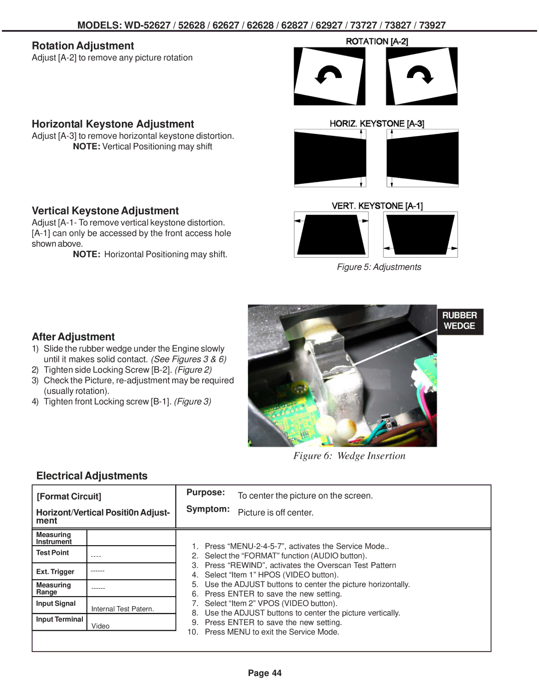
Rotation Adjustment
Adjust
Horizontal Keystone Adjustment
Adjust
NOTE: Vertical Positioning may shift
Vertical Keystone Adjustment
Adjust
NOTE: Horizontal Positioning may shift.
Figure 5: Adjustments
After Adjustment
1)Slide the rubber wedge under the Engine slowly until it makes solid contact. (See Figures 3 & 6)
2)Tighten side Locking Screw
3)Check the Picture,
4)Tighten front Locking screw
RUBBER WEDGE
Figure 6: Wedge Insertion
Electrical Adjustments
[Format Circuit]
Horizont/Vertical Positi0n Adjust- ment
Purpose: To center the picture on the screen.
Symptom: Picture is off center.
Measuring |
| |
Instrument |
| |
Test Point | ||
| ||
|
| |
Ext. Trigger | ||
|
| |
Measuring | ||
Range | ||
| ||
Input Signal | Internal Test Patern. | |
|
Input Terminal
Video
1.Press
2.Select the “FORMAT” function (AUDIO button).
3.Press “REWIND”, activates the Overscan Test Pattern
4.Select “Item 1” HPOS (VIDEO button).
5.Use the ADJUST buttons to center the picture horizontally.
6.Press ENTER to save the new setting.
7.Select “Item 2” VPOS (VIDEO button).
8.Use the ADJUST buttons to center the picture vertically.
9.Press ENTER to save the new setting.
10.Press MENU to exit the Service Mode.
Page 44