MODELS:
OPTICAL ENGINE REPLACEMENT (Details)
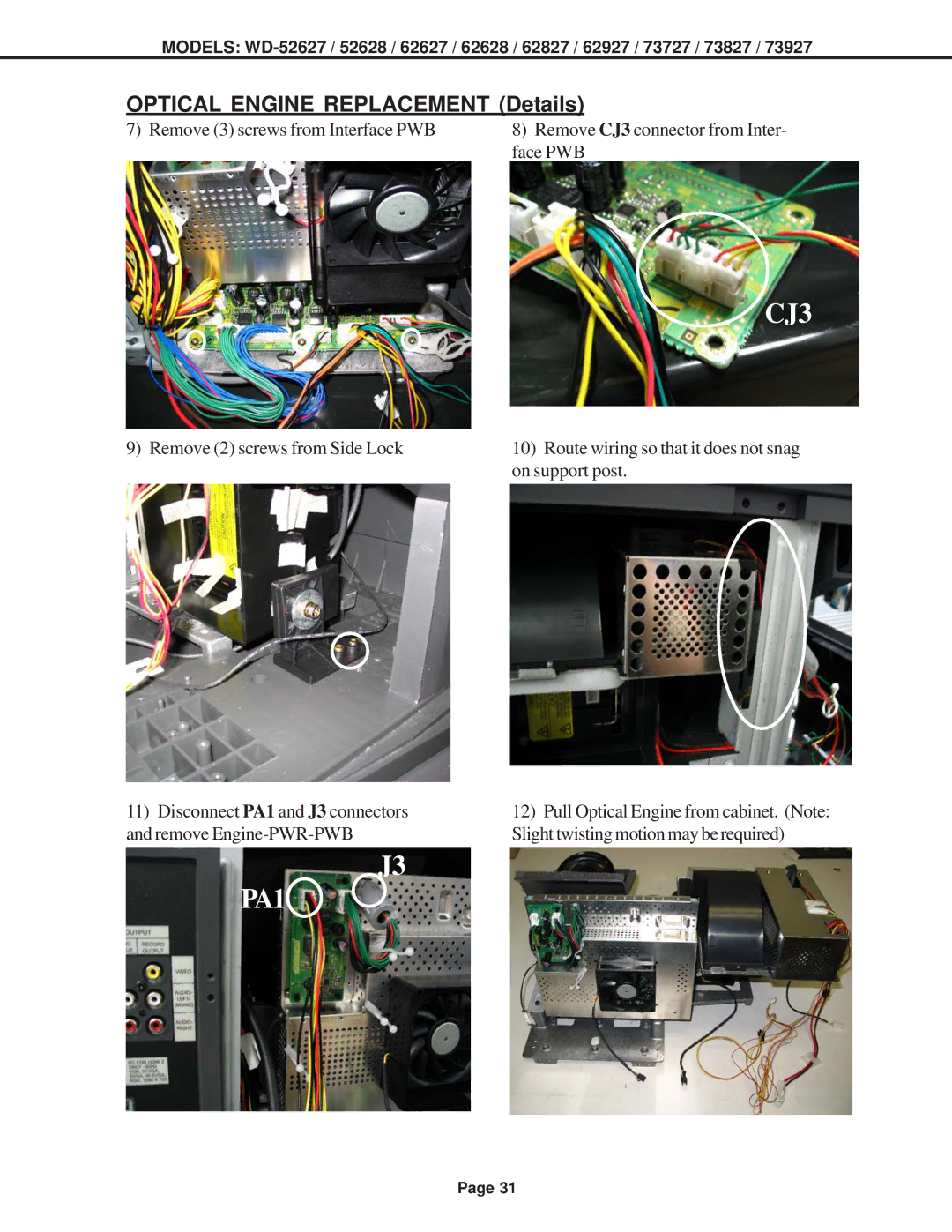
7) Remove (3) screws from Interface PWB | 8) Remove CJ3 connector from Inter- |
| face PWB |
CJ3
9) Remove (2) screws from Side Lock | 10) Route wiring so that it does not snag |
| on support post. |
11)Disconnect PA1 and J3 connectors and remove
J3
PA1
12)Pull Optical Engine from cabinet. (Note: Slight twisting motion may be required)
Page 31