1. Television Overview | 9 |
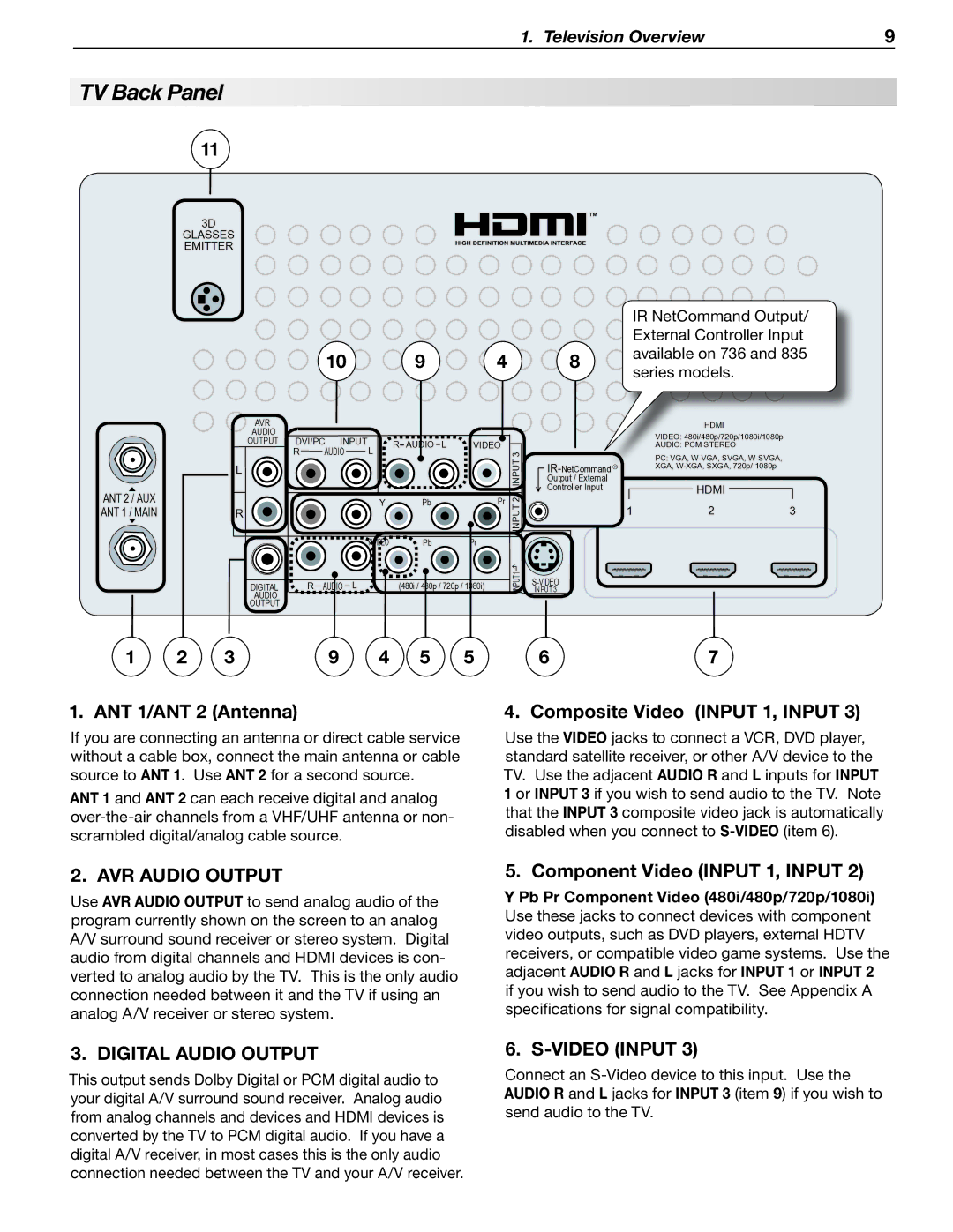
TV Back Panel
11
3D
GLASSES EMITTER
|
|
|
| IR NetCommand Output/ | |
|
|
|
| External Controller Input | |
10 | 9 | 4 | 8 | available on 736 and 835 | |
series models. | |||||
|
|
|
|
| AVR |
|
|
|
|
|
|
|
|
|
|
| AUDIO |
|
|
|
|
|
|
|
|
|
|
| OUTPUT | DVI/PC | INPUT | R | AUDIO | L | VIDEO |
|
| ||
|
| R | AUDIO | L | 3 |
| |||||
|
|
|
|
|
|
| |||||
| L |
|
|
|
|
|
|
|
| INPUT | |
|
|
|
|
|
|
|
|
|
|
| Output / External |
ANT 2 / AUX |
|
|
|
|
|
|
|
|
|
| Controller Input |
R |
|
|
| Y |
| Pb |
| Pr | 2 |
| |
ANT 1 / MAIN |
|
|
|
|
|
|
|
| INPUT |
| |
|
|
|
|
|
|
|
|
|
|
| |
|
|
|
|
| Y/VIDEO |
| Pb |
| Pr |
|
|
| DIGITAL | R | AUDIO | L | (480i / 480p / 720p / 1080i) | 1 | INPUT 3 | ||||
| INPUT | ||||||||||
|
|
|
|
|
|
|
|
|
|
| |
| AUDIO |
|
|
|
|
|
|
|
|
|
|
| OUTPUT |
|
|
|
|
|
|
|
|
|
|
1 | 2 | 3 | 9 | 4 | 5 | 5 | 6 |
HDMI
VIDEO: 480i/480p/720p/1080i/1080p
AUDIO: PCM STEREO
PC: VGA,
| HDMI |
|
1 | 2 | 3 |
7
1. ANT 1/ANT 2 (Antenna)
If you are connecting an antenna or direct cable service without a cable box, connect the main antenna or cable source to ANT 1. Use ANT 2 for a second source.
ANT 1 and ANT 2 can each receive digital and analog
4. Composite Video (INPUT 1, INPUT 3)
Use the VIDEO jacks to connect a VCR, DVD player, standard satellite receiver, or other A/V device to the TV. Use the adjacent AUDIO R and L inputs for INPUT 1 or INPUT 3 if you wish to send audio to the TV. Note that the INPUT 3 composite video jack is automatically disabled when you connect to
2. AVR AUDIO OUTPUT
Use AVR AUDIO OUTPUT to send analog audio of the program currently shown on the screen to an analog A/V surround sound receiver or stereo system. Digital audio from digital channels and HDMI devices is con- verted to analog audio by the TV. This is the only audio connection needed between it and the TV if using an analog A/V receiver or stereo system.
5. Component Video (INPUT 1, INPUT 2)
Y Pb Pr Component Video (480i/480p/720p/1080i) Use these jacks to connect devices with component video outputs, such as DVD players, external HDTV receivers, or compatible video game systems. Use the adjacent AUDIO R and L jacks for INPUT 1 or INPUT 2 if you wish to send audio to the TV. See Appendix A specifications for signal compatibility.
3. DIGITAL AUDIO OUTPUT
This output sends Dolby Digital or PCM digital audio to your digital A/V surround sound receiver. Analog audio from analog channels and devices and HDMI devices is converted by the TV to PCM digital audio. If you have a digital A/V receiver, in most cases this is the only audio connection needed between the TV and your A/V receiver.
6. S-VIDEO (INPUT 3)
Connect an
