Preparing your projector (continued)
Overview
1 | 2 | 3 | 4 | 5 | 8 | 13 |
6 | 7 | 9 | 10 | 11 | 12 |
Caution:
Do not replace the lamp immediately after using the projector because the lamp would be extremely hot and it may cause burns.
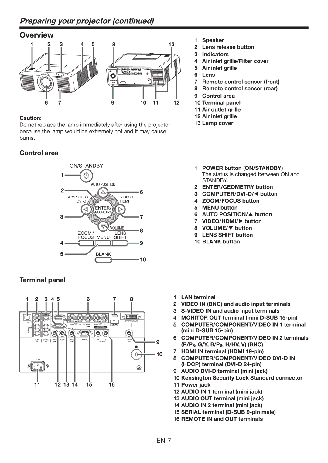
1 Speaker
2Lens release button
3 Indicators
4 Air inlet grille/Filter cover
5 Air inlet grille
6 Lens
7 Remote control sensor (front)
8 Remote control sensor (rear)
9 Control area
10 Terminal panel
11 Air outlet grille
12 Air inlet grille
13 Lamp cover
Control area
|
| 1 | POWER button (ON/STANDBY) | |
1 |
|
| The status is changed between ON and | |
|
|
| STANDBY. | |
2 | 6 | 2 | ENTER/GEOMETRY button | |
3 | ||||
| ||||
|
| |||
|
| 4 | ZOOM/FOCUS button | |
|
| 5 | MENU button | |
3 | 7 | 6 | AUTO POSITION/ button | |
7 | VIDEO/HDMI/ button | |||
|
| |||
| 8 | 8 | VOLUME/ button | |
| 9 | LENS SHIFT button | ||
|
| |||
4 | 9 | 10 | BLANK button | |
5 | 10 |
|
| |
|
|
|
Terminal panel |
|
|
|
|
|
| |||
1 | 2 | 3 | 4 5 | 6 | 7 | 8 |
| 1 | LAN terminal |
| 2 | VIDEO IN (BNC) and audio input terminals | |||||||
|
|
|
|
|
|
|
| ||
|
|
|
|
|
|
|
| 3 | |
|
|
|
|
|
|
|
| 4 | MONITOR OUT terminal (mini |
|
|
|
|
|
|
|
| 5 | COMPUTER/COMPONENT/VIDEO IN 1 terminal |
|
|
|
|
|
|
|
|
| (mini |
|
|
|
|
|
|
| 9 | 6 | COMPUTER/COMPONENT/VIDEO IN 2 terminals |
|
|
|
|
|
|
|
| (R/PR, G/Y, B/PB, H/HV, V) (BNC) | |
|
|
|
|
|
|
|
|
| |
|
|
|
|
|
|
| 10 | 7 | HDMI IN terminal (HDMI |
|
|
|
|
|
|
| 8 | COMPUTER/COMPONENT/VIDEO | |
|
|
|
|
|
|
|
| ||
|
|
|
|
|
|
|
|
| (HDCP) terminal |
|
|
|
|
|
|
|
| 9 | AUDIO |
|
|
|
|
|
|
|
| 10 | Kensington Security Lock Standard connector |
| 11 |
| 12 13 14 | 15 | 16 |
|
| 11 | Power jack |
|
|
|
|
|
|
|
| 12 | AUDIO IN 1 terminal (mini jack) |
|
|
|
|
|
|
|
| 13 | AUDIO OUT terminal (mini jack) |
|
|
|
|
|
|
|
| 14 | AUDIO IN 2 terminal (mini jack) |
|
|
|
|
|
|
|
| 15 | SERIAL terminal |
|
|
|
|
|
|
|
| 16 | REMOTE IN and OUT terminals |