Startup and Operation
2
Introduction
This chapter gives you information about the:
■
■Runtime switches and indicators
Applying Power
After you verify that all necessary hardware preparation is complete and all connections are made correctly, you can apply power to the system.
When you are ready to apply power to the MVME3100:
■Verify that the chassis power supply voltage setting matches the voltage present in the country of use (if the power supply in your system is not
■On powering up, the MVME3100 brings up the MOTLoad prompt, MVME3100>
Switches and Indicators
The MVME3100 board provides a single push button switch that provides both abort and reset (ABT/RST) functions. When the switch is pressed for less than five seconds, an abort interrupt is generated to the processor. If the switch is held for more than five seconds, a board hard reset is generated. The board hard reset will reset the MPC8540, local
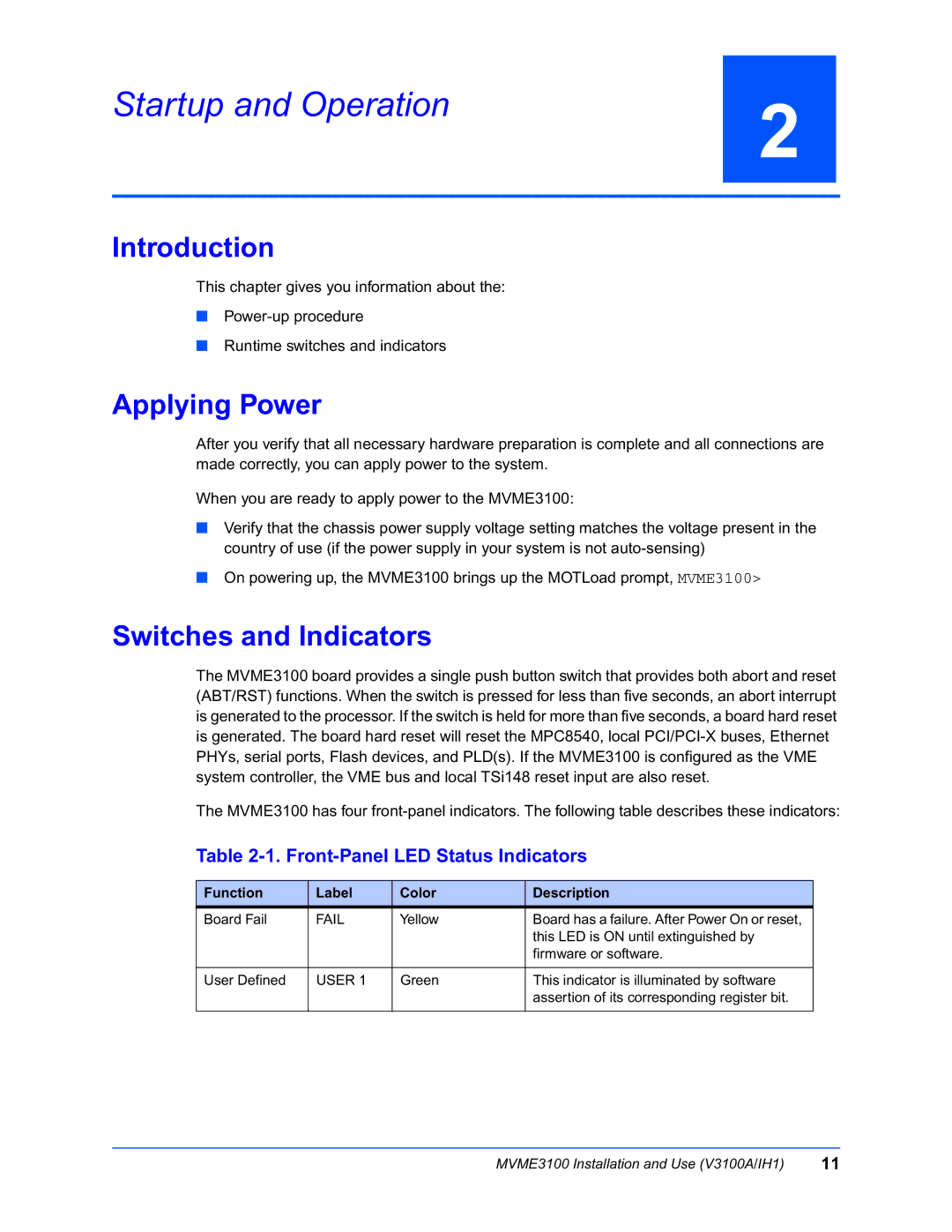
The MVME3100 has four
Table 2-1. Front-Panel LED Status Indicators
Function | Label | Color | Description |
Board Fail | FAIL | Yellow | Board has a failure. After Power On or reset, |
|
|
| this LED is ON until extinguished by |
|
|
| firmware or software. |
|
|
|
|
User Defined | USER 1 | Green | This indicator is illuminated by software |
|
|
| assertion of its corresponding register bit. |
|
|
|
|
MVME3100 Installation and Use (V3100A/IH1) | 11 |