Chapter 5 Pin Assignments
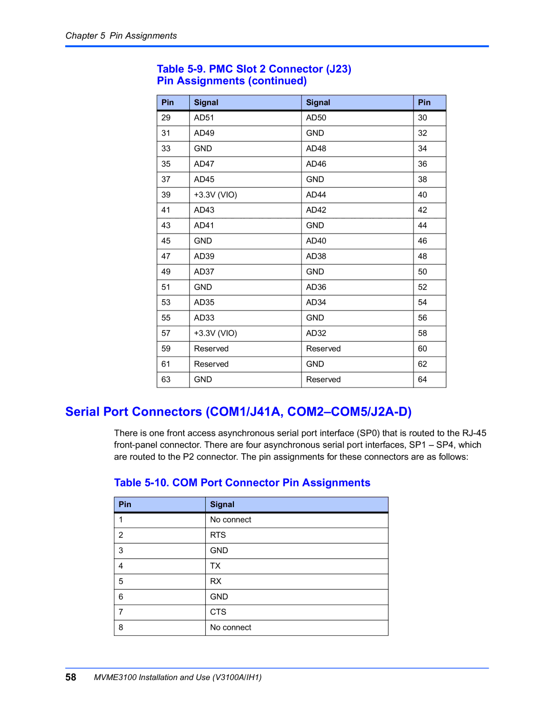
Table 5-9. PMC Slot 2 Connector (J23)
Pin Assignments (continued)
Pin | Signal | Signal | Pin |
29 | AD51 | AD50 | 30 |
|
|
|
|
31 | AD49 | GND | 32 |
|
|
|
|
33 | GND | AD48 | 34 |
|
|
|
|
35 | AD47 | AD46 | 36 |
|
|
|
|
37 | AD45 | GND | 38 |
|
|
|
|
39 | +3.3V (VIO) | AD44 | 40 |
|
|
|
|
41 | AD43 | AD42 | 42 |
|
|
|
|
43 | AD41 | GND | 44 |
|
|
|
|
45 | GND | AD40 | 46 |
|
|
|
|
47 | AD39 | AD38 | 48 |
|
|
|
|
49 | AD37 | GND | 50 |
|
|
|
|
51 | GND | AD36 | 52 |
|
|
|
|
53 | AD35 | AD34 | 54 |
|
|
|
|
55 | AD33 | GND | 56 |
|
|
|
|
57 | +3.3V (VIO) | AD32 | 58 |
|
|
|
|
59 | Reserved | Reserved | 60 |
|
|
|
|
61 | Reserved | GND | 62 |
|
|
|
|
63 | GND | Reserved | 64 |
|
|
|
|
Serial Port Connectors (COM1/J41A, COM2–COM5/J2A-D)
There is one front access asynchronous serial port interface (SP0) that is routed to the
Table 5-10. COM Port Connector Pin Assignments
Pin
1
2
3
4
5
6
7
8
Signal
No connect
RTS
GND
TX
RX
GND
CTS
No connect
58MVME3100 Installation and Use (V3100A/IH1)
