Chapter 4 Functional Description
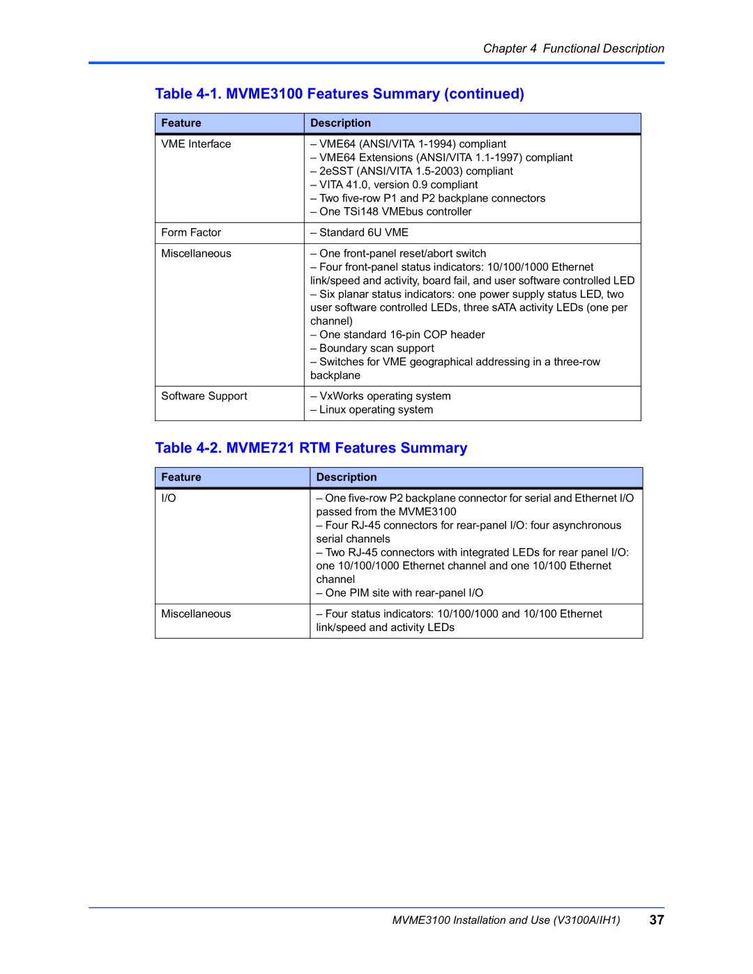
Table 4-1. MVME3100 Features Summary (continued)
Feature | Description |
VME Interface | – VME64 (ANSI/VITA |
| – VME64 Extensions (ANSI/VITA |
| – 2eSST (ANSI/VITA |
| – VITA 41.0, version 0.9 compliant |
| – Two |
| – One TSi148 VMEbus controller |
|
|
Form Factor | – Standard 6U VME |
|
|
Miscellaneous | – One |
| – Four |
| link/speed and activity, board fail, and user software controlled LED |
| – Six planar status indicators: one power supply status LED, two |
| user software controlled LEDs, three sATA activity LEDs (one per |
| channel) |
| – One standard |
| – Boundary scan support |
| – Switches for VME geographical addressing in a |
| backplane |
|
|
Software Support | – VxWorks operating system |
| – Linux operating system |
|
|
Table 4-2. MVME721 RTM Features Summary
Feature | Description |
I/O | – One |
| passed from the MVME3100 |
| – Four |
| serial channels |
| – Two |
| one 10/100/1000 Ethernet channel and one 10/100 Ethernet |
| channel |
| – One PIM site with |
|
|
Miscellaneous | – Four status indicators: 10/100/1000 and 10/100 Ethernet |
| link/speed and activity LEDs |
|
|
MVME3100 Installation and Use (V3100A/IH1) | 37 |