Chapter 4 Functional Description
PCI-X-to-PCI-X Bridges
The MVME3100 uses two PLX PCI6520
PCI Mezzanine Card Slots
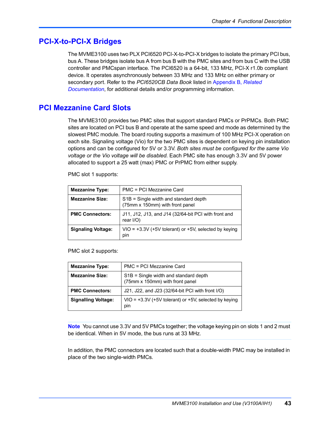
The MVME3100 provides two PMC sites that support standard PMCs or PrPMCs. Both PMC sites are located on PCI bus B and operate at the same speed and mode as determined by the slowest PMC module. The board routing supports a maximum of 100 MHz
PMC slot 1 supports:
Mezzanine Type: | PMC = PCI Mezzanine Card |
|
|
Mezzanine Size: | S1B = Single width and standard depth |
| (75mm x 150mm) with front panel |
|
|
PMC Connectors: | J11, J12, J13, and J14 |
| rear I/O) |
|
|
Signaling Voltage: | VIO = +3.3V (+5V tolerant) or +5V, selected by keying |
| pin |
|
|
PMC slot 2 supports:
Mezzanine Type: | PMC = PCI Mezzanine Card |
|
|
Mezzanine Size: | S1B = Single width and standard depth |
| (75mm x 150mm) with front panel |
|
|
PMC Connectors: | J21, J22, and J23 |
|
|
Signalling Voltage: | VIO = +3.3V (+5V tolerant) or +5V, selected by keying |
| pin |
|
|
Note You cannot use 3.3V and 5V PMCs together; the voltage keying pin on slots 1 and 2 must be identical. When in 5V mode, the bus runs at 33 MHz.
In addition, the PMC connectors are located such that a
MVME3100 Installation and Use (V3100A/IH1) | 43 |
