Functional Description
4
This chapter describes the MVME3100 and the MVME721 rear transition module (RTM) on a block diagram level.
Features
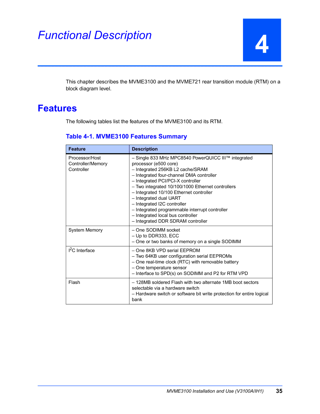
The following tables list the features of the MVME3100 and its RTM.
Table 4-1. MVME3100 Features Summary
Feature | Description |
Processor/Host | – Single 833 MHz MPC8540 PowerQUICC III™ integrated |
Controller/Memory | processor (e500 core) |
Controller | – Integrated 256KB L2 cache/SRAM |
| – Integrated |
| – Integrated |
| – Two integrated 10/100/1000 Ethernet controllers |
| – Integrated 10/100 Ethernet controller |
| – Integrated dual UART |
| – Integrated I2C controller |
| – Integrated programmable interrupt controller |
| – Integrated local bus controller |
| – Integrated DDR SDRAM controller |
|
|
System Memory | – One SODIMM socket |
| – Up to DDR333, ECC |
| – One or two banks of memory on a single SODIMM |
|
|
I2C Interface | – One 8KB VPD serial EEPROM |
| – Two 64KB user configuration serial EEPROMs |
| – One |
| – One temperature sensor |
| – Interface to SPD(s) on SODIMM and P2 for RTM VPD |
|
|
Flash | – 128MB soldered Flash with two alternate 1MB boot sectors |
| selectable via a hardware switch |
| – Hardware switch or software bit write protection for entire logical |
| bank |
|
|
MVME3100 Installation and Use (V3100A/IH1) | 35 |