Chapter 5 Pin Assignments
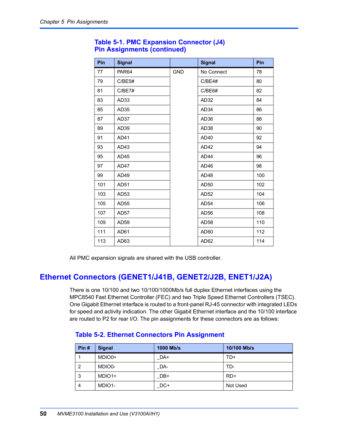
Table 5-1. PMC Expansion Connector (J4)
Pin Assignments (continued)
Pin | Signal |
| Signal | Pin |
77 | PAR64 | GND | No Connect | 78 |
|
|
|
|
|
79 | C/BE5# |
| C/BE4# | 80 |
|
|
|
|
|
81 | C/BE7# |
| C/BE6# | 82 |
|
|
|
|
|
83 | AD33 |
| AD32 | 84 |
|
|
|
|
|
85 | AD35 |
| AD34 | 86 |
|
|
|
|
|
87 | AD37 |
| AD36 | 88 |
|
|
|
|
|
89 | AD39 |
| AD38 | 90 |
|
|
|
|
|
91 | AD41 |
| AD40 | 92 |
|
|
|
|
|
93 | AD43 |
| AD42 | 94 |
|
|
|
|
|
95 | AD45 |
| AD44 | 96 |
|
|
|
|
|
97 | AD47 |
| AD46 | 98 |
|
|
|
|
|
99 | AD49 |
| AD48 | 100 |
|
|
|
|
|
101 | AD51 |
| AD50 | 102 |
|
|
|
|
|
103 | AD53 |
| AD52 | 104 |
|
|
|
|
|
105 | AD55 |
| AD54 | 106 |
|
|
|
|
|
107 | AD57 |
| AD56 | 108 |
|
|
|
|
|
109 | AD59 |
| AD58 | 110 |
|
|
|
|
|
111 | AD61 |
| AD60 | 112 |
|
|
|
|
|
113 | AD63 |
| AD62 | 114 |
|
|
|
|
|
All PMC expansion signals are shared with the USB controller.
Ethernet Connectors (GENET1/J41B, GENET2/J2B, ENET1/J2A)
There is one 10/100 and two 10/100/1000Mb/s full duplex Ethernet interfaces using the MPC8540 Fast Ethernet Controller (FEC) and two Triple Speed Ethernet Controllers (TSEC). One Gigabit Ethernet interface is routed to a
Table 5-2. Ethernet Connectors Pin Assignment
Pin # | Signal | 1000 Mb/s | 10/100 Mb/s |
1 | MDIO0+ | _DA+ | TD+ |
|
|
|
|
2 | MDIO0- | _DA- | TD- |
|
|
|
|
3 | MDIO1+ | _DB+ | RD+ |
|
|
|
|
4 | MDIO1- | _DC+ | Not Used |
|
|
|
|
50MVME3100 Installation and Use (V3100A/IH1)