Chapter 5 Pin Assignments
sATA Connectors (J28 and J29)
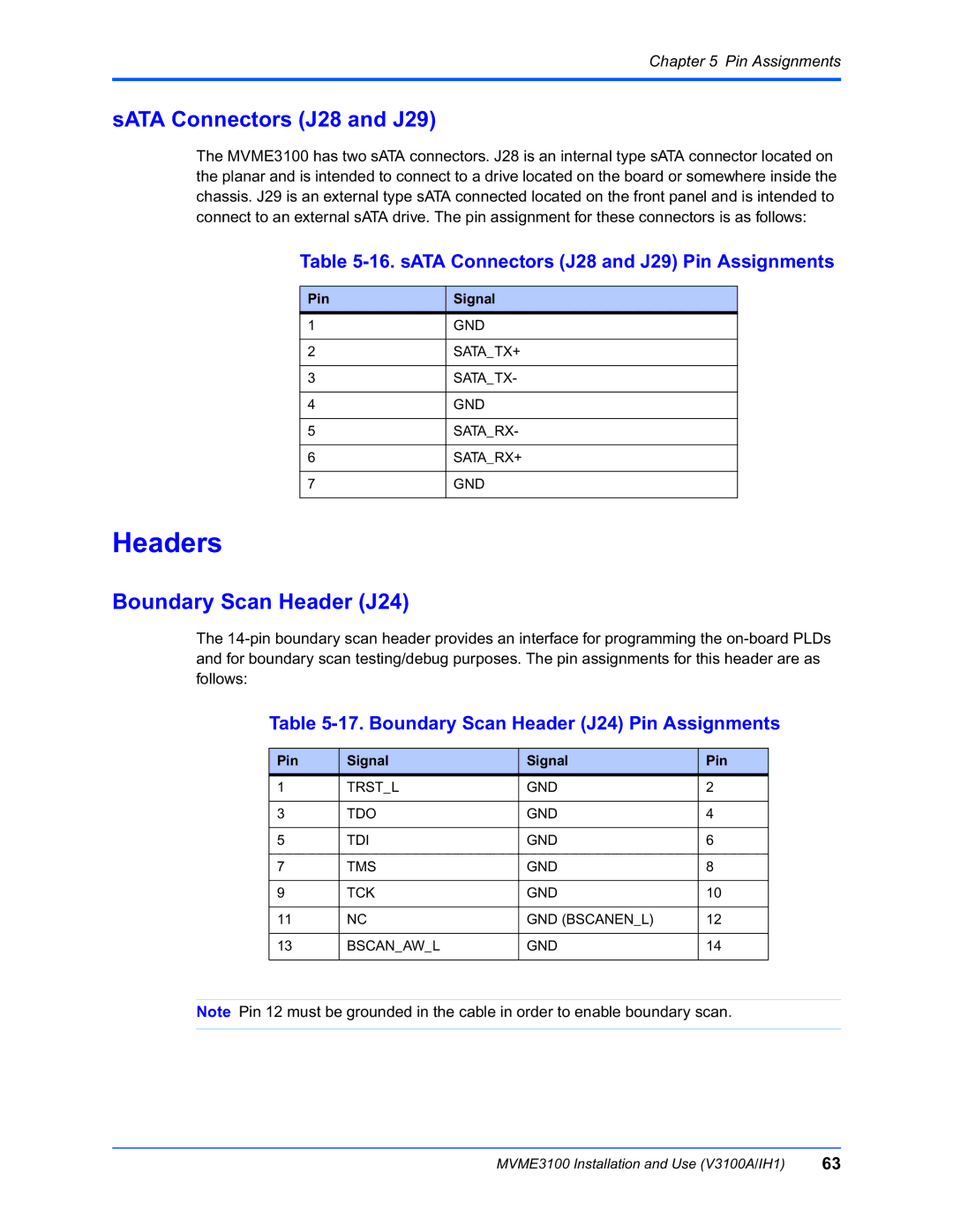
The MVME3100 has two sATA connectors. J28 is an internal type sATA connector located on the planar and is intended to connect to a drive located on the board or somewhere inside the chassis. J29 is an external type sATA connected located on the front panel and is intended to connect to an external sATA drive. The pin assignment for these connectors is as follows:
Table 5-16. sATA Connectors (J28 and J29) Pin Assignments
Pin
1
2
3
4
5
6
7
Signal
GND
SATA_TX+
SATA_TX-
GND
SATA_RX-
SATA_RX+
GND
Headers
Boundary Scan Header (J24)
The
Table 5-17. Boundary Scan Header (J24) Pin Assignments
Pin | Signal | Signal | Pin |
1 | TRST_L | GND | 2 |
|
|
|
|
3 | TDO | GND | 4 |
|
|
|
|
5 | TDI | GND | 6 |
|
|
|
|
7 | TMS | GND | 8 |
|
|
|
|
9 | TCK | GND | 10 |
|
|
|
|
11 | NC | GND (BSCANEN_L) | 12 |
|
|
|
|
13 | BSCAN_AW_L | GND | 14 |
|
|
|
|
Note Pin 12 must be grounded in the cable in order to enable boundary scan.
MVME3100 Installation and Use (V3100A/IH1) | 63 |