Chapter 2 Startup and Operation
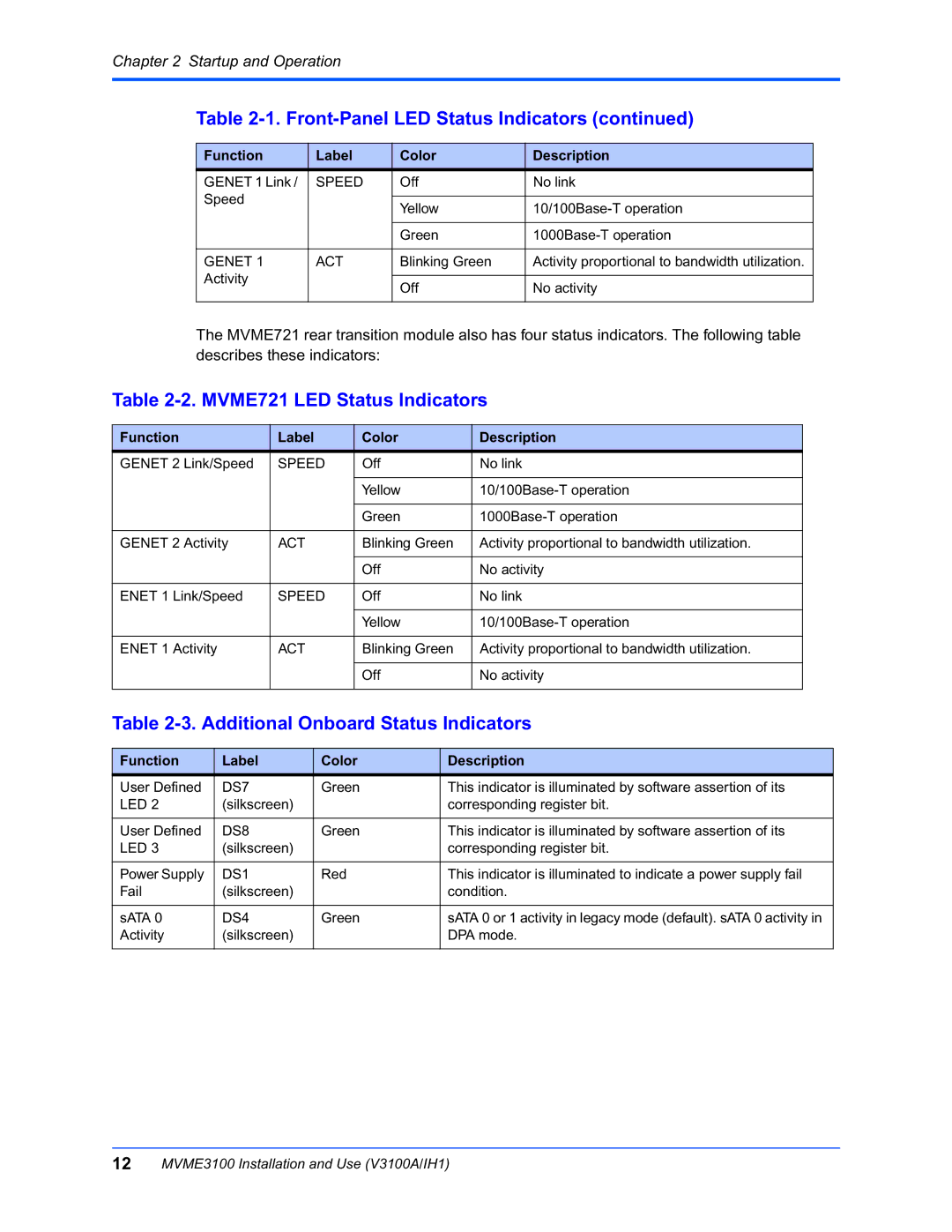
Table 2-1. Front-Panel LED Status Indicators (continued)
|
| Function |
| Label |
|
| Color |
|
|
| Description |
| |||
|
| GENET 1 Link / | SPEED |
| Off |
|
|
| No link |
| |||||
|
| Speed |
|
|
|
|
|
|
|
|
|
|
|
| |
|
|
|
|
|
|
| Yellow |
|
|
|
| ||||
|
|
|
|
|
|
|
|
|
|
|
|
| |||
|
|
|
|
|
|
|
|
|
|
|
|
|
|
|
|
|
|
|
|
|
|
|
|
| Green |
|
|
|
| ||
|
|
|
|
|
|
|
|
|
|
|
|
|
|
|
|
|
| GENET 1 |
| ACT |
|
| Blinking Green |
| Activity proportional to bandwidth utilization. |
| |||||
|
| Activity |
|
|
|
|
|
|
|
|
|
|
|
| |
|
|
|
|
|
|
| Off |
|
|
| No activity |
| |||
|
|
|
|
|
|
|
|
|
|
|
|
| |||
|
|
|
|
|
|
|
|
|
|
|
| ||||
| The MVME721 rear transition module also has four status indicators. The following table | ||||||||||||||
| describes these indicators: |
|
|
|
|
|
|
| |||||||
Table |
|
|
| ||||||||||||
|
|
|
|
|
|
|
|
|
|
| |||||
Function |
|
| Label |
| Color |
|
| Description |
|
| |||||
GENET 2 Link/Speed | SPEED |
| Off |
|
| No link |
|
|
| ||||||
|
|
|
|
|
|
|
|
|
|
| |||||
|
|
|
|
|
|
| Yellow |
|
|
| |||||
|
|
|
|
|
|
|
|
|
|
| |||||
|
|
|
|
|
|
| Green |
|
|
| |||||
|
|
|
|
|
|
|
|
| |||||||
GENET 2 Activity | ACT |
| Blinking Green | Activity proportional to bandwidth utilization. |
|
| |||||||||
|
|
|
|
|
|
|
|
|
|
|
| ||||
|
|
|
|
|
|
| Off |
|
| No activity |
|
| |||
|
|
|
|
|
|
|
|
|
|
|
| ||||
ENET 1 Link/Speed | SPEED |
| Off |
|
| No link |
|
|
| ||||||
|
|
|
|
|
|
|
|
|
|
| |||||
|
|
|
|
|
|
| Yellow |
|
|
| |||||
|
|
|
|
|
|
|
|
| |||||||
ENET 1 Activity | ACT |
| Blinking Green | Activity proportional to bandwidth utilization. |
|
| |||||||||
|
|
|
|
|
|
|
|
|
|
|
| ||||
|
|
|
|
|
|
| Off |
|
| No activity |
|
| |||
|
|
|
|
|
|
|
|
|
| ||||||
Table |
|
|
| ||||||||||||
|
|
|
|
|
|
|
|
|
|
|
|
|
| ||
Function |
| Label |
| Color |
|
|
| Description |
|
|
| ||||
User Defined |
| DS7 |
| Green |
|
|
| This indicator is illuminated by software assertion of its | |||||||
LED 2 |
| (silkscreen) |
|
|
|
| corresponding register bit. | ||||||||
|
|
|
|
|
|
|
|
| |||||||
User Defined |
| DS8 |
| Green |
|
|
| This indicator is illuminated by software assertion of its | |||||||
LED 3 |
| (silkscreen) |
|
|
|
| corresponding register bit. | ||||||||
|
|
|
|
|
|
|
|
| |||||||
Power Supply |
| DS1 |
| Red |
|
|
| This indicator is illuminated to indicate a power supply fail | |||||||
Fail |
| (silkscreen) |
|
|
|
| condition. |
|
|
| |||||
|
|
|
|
|
|
|
|
| |||||||
sATA 0 |
| DS4 |
| Green |
|
|
| sATA 0 or 1 activity in legacy mode (default). sATA 0 activity in | |||||||
Activity |
| (silkscreen) |
|
|
|
| DPA mode. |
|
|
| |||||
|
|
|
|
|
|
|
|
|
|
|
|
|
|
|
|
12MVME3100 Installation and Use (V3100A/IH1)