Introduction |
Hardware Block Diagram
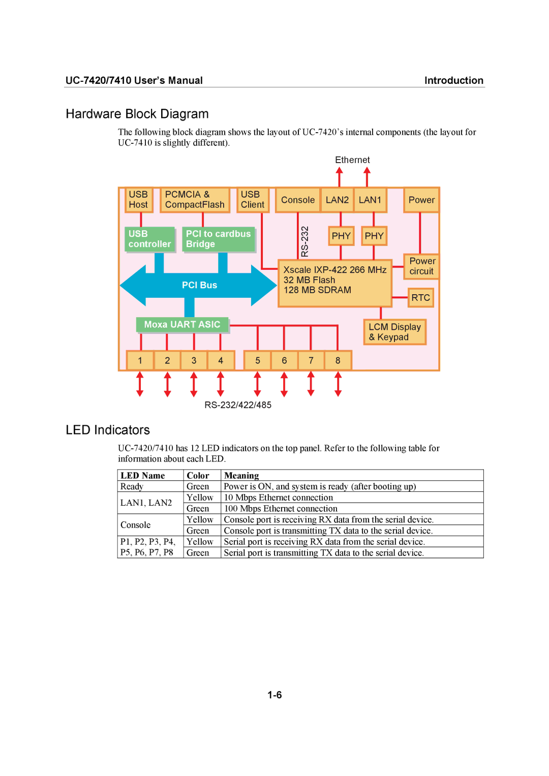
The following block diagram shows the layout of
Ethernet
USB | PCMCIA & | USB |
Host | CompactFlash | Client |
| USB |
| PCI to cardbus | ||||
| controller |
| Bridge | ||||
|
|
|
|
|
|
|
|
PCI Bus
|
|
|
|
|
|
|
|
|
Console | LAN2 | LAN1 | ||||||
|
|
|
|
|
|
|
|
|
| 232 |
|
|
|
|
|
|
|
|
| PHY |
| PHY | ||||
| RS- |
|
|
|
|
|
|
|
|
|
|
|
|
|
|
| |
|
|
|
|
|
|
|
|
|
Xscale
32 MB Flash
128 MB SDRAM
Power |
Power |
circuit |
![]()
![]() RTC
RTC
| Moxa UART ASIC |
| ||
1 | 2 | 3 | 4 | 5 |
LCM Display
& Keypad
6 ![]() 7
7 ![]() 8
8
LED Indicators
LED Name | Color | Meaning | |
Ready | Green | Power is ON, and system is ready (after booting up) | |
LAN1, LAN2 | Yellow | 10 Mbps Ethernet connection | |
Green | 100 Mbps Ethernet connection | ||
| |||
Console | Yellow | Console port is receiving RX data from the serial device. | |
Green | Console port is transmitting TX data to the serial device. | ||
| |||
P1, P2, P3, P4, | Yellow | Serial port is receiving RX data from the serial device. | |
P5, P6, P7, P8 | Green | Serial port is transmitting TX data to the serial device. |