Maxim DS33Z41 specifications TAP Controller State Diagram, Instruction Register

Models: DS33Z41

1 167
Download 167 pages 14.56 Kb
Page 162
Image 162

DS33Z41 Quad IMUX Ethernet Mapper

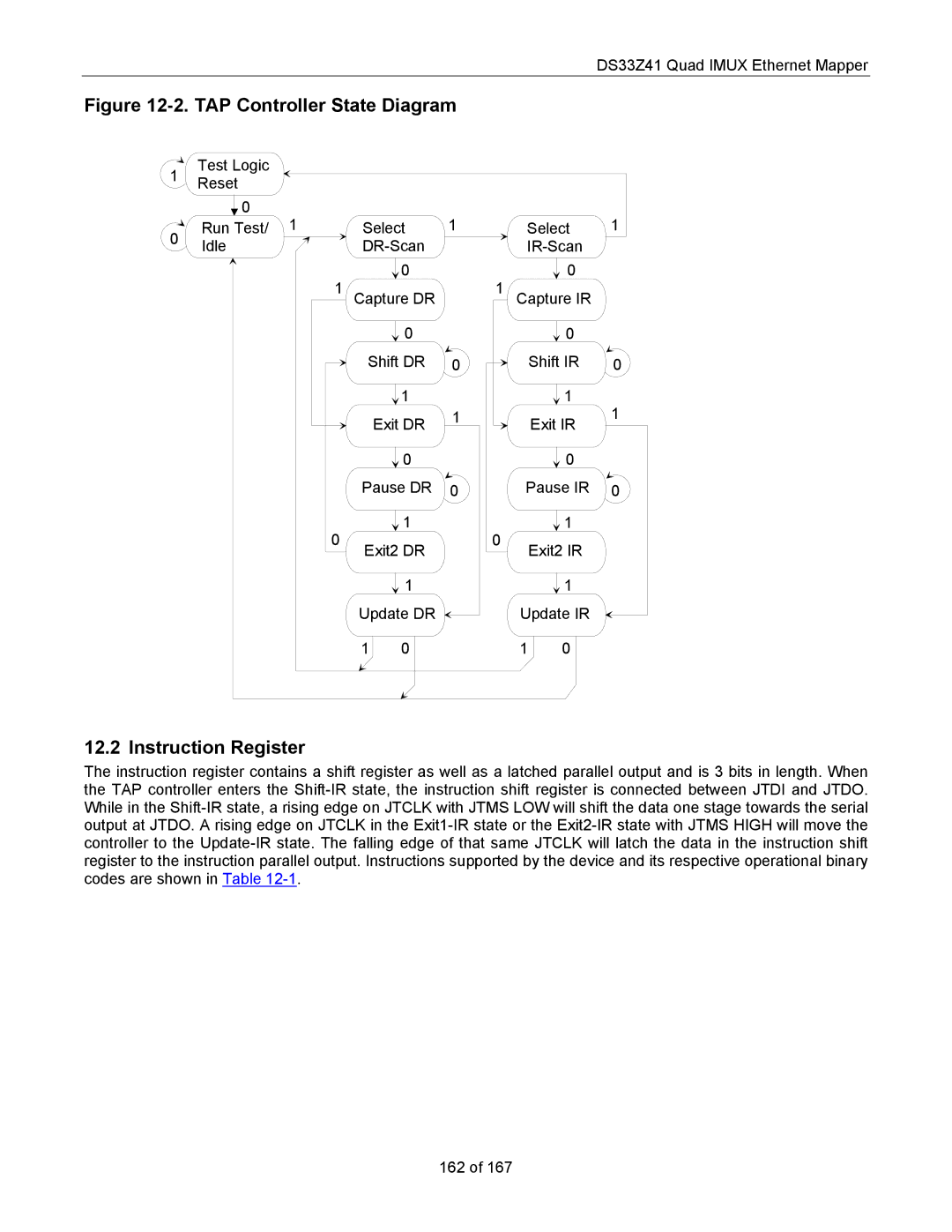
Figure 12-2. TAP Controller State Diagram

1

Test Logic


Reset


0

1


1


1

0

Run Test/

Select


Select

Idle


DR-Scan


IR-Scan


1

0


1

0


Capture DR


Capture IR


0


0


Shift DR

0


Shift IR

0


1


1

1


Exit DR

1


Exit IR


0


0


Pause DR

0

Pause IR

0

0


1


0

1


Exit2 DR


Exit2 IR


1


1


Update DR


Update IR


1

0


1

0


12.2 Instruction Register

The instruction register contains a shift register as well as a latched parallel output and is 3 bits in length. When the TAP controller enters the Shift-IR state, the instruction shift register is connected between JTDI and JTDO. While in the Shift-IR state, a rising edge on JTCLK with JTMS LOW will shift the data one stage towards the serial output at JTDO. A rising edge on JTCLK in the Exit1-IR state or the Exit2-IR state with JTMS HIGH will move the controller to the Update-IR state. The falling edge of that same JTCLK will latch the data in the instruction shift register to the instruction parallel output. Instructions supported by the device and its respective operational binary codes are shown in Table 12-1.

162 of 167

Page 162
Image 162
Maxim DS33Z41 specifications TAP Controller State Diagram, Instruction Register