DS33Z41 Quad IMUX Ethernet Mapper
8.9.2IMUX Command Protocol
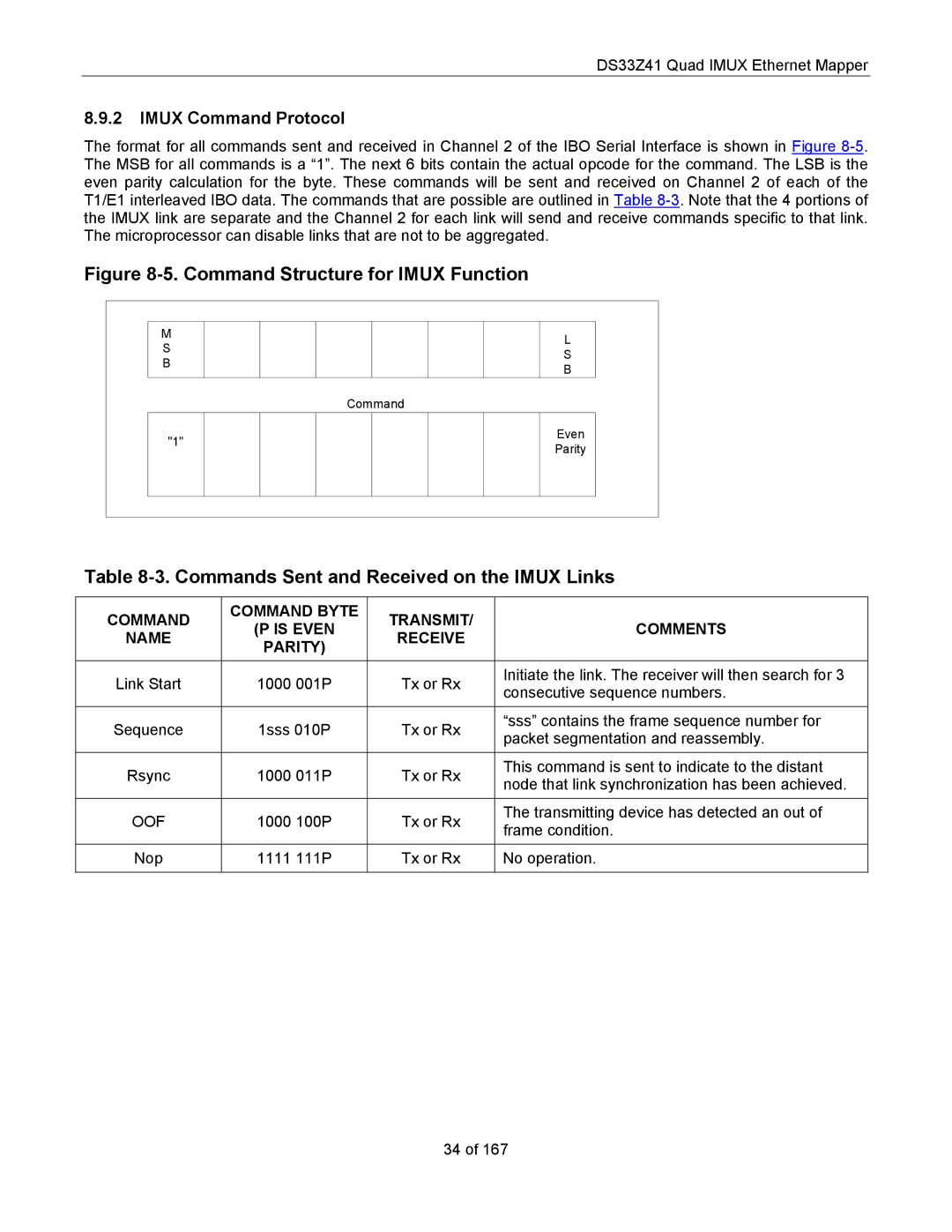
The format for all commands sent and received in Channel 2 of the IBO Serial Interface is shown in Figure
Figure 8-5. Command Structure for IMUX Function
M
S
B
"1"
L
S
B
Command
Even
Parity
Table 8-3. Commands Sent and Received on the IMUX Links
COMMAND | COMMAND BYTE | TRANSMIT/ | COMMENTS | |
(P IS EVEN | ||||
NAME | RECEIVE | |||
PARITY) |
| |||
|
|
| ||
|
|
|
| |
Link Start | 1000 001P | Tx or Rx | Initiate the link. The receiver will then search for 3 | |
consecutive sequence numbers. | ||||
|
|
| ||
Sequence | 1sss 010P | Tx or Rx | “sss” contains the frame sequence number for | |
packet segmentation and reassembly. | ||||
|
|
| ||
|
|
|
| |
Rsync | 1000 011P | Tx or Rx | This command is sent to indicate to the distant | |
node that link synchronization has been achieved. | ||||
|
|
| ||
|
|
|
| |
OOF | 1000 100P | Tx or Rx | The transmitting device has detected an out of | |
frame condition. | ||||
|
|
| ||
Nop | 1111 111P | Tx or Rx | No operation. | |
|
|
|
|
34 of 167