DS33Z41 Quad IMUX Ethernet Mapper
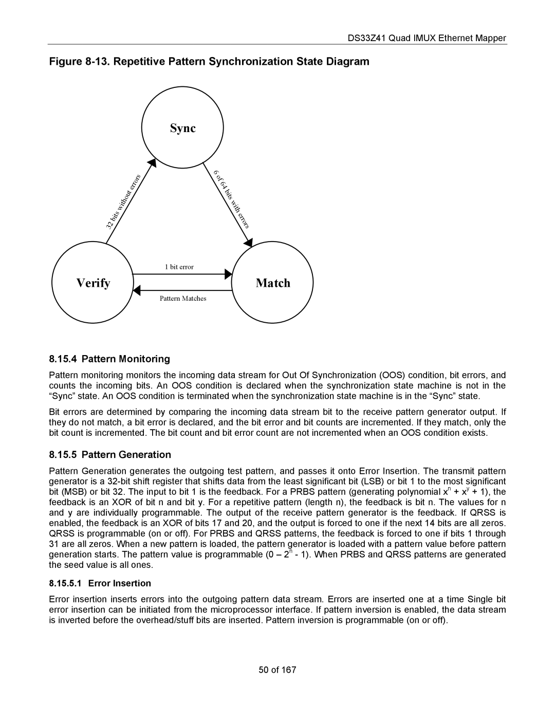
Figure 8-13. Repetitive Pattern Synchronization State Diagram
Sync
|
|
|
|
|
|
|
|
|
|
|
| r | o | r | s |
|
|
|
|
|
|
|
|
|
|
| r |
| |||
|
|
|
|
|
|
|
|
| t | e |
|
| |||
|
|
|
|
|
|
|
| u |
|
|
|
| |||
|
|
|
|
|
|
|
|
|
|
|
|
| |||
|
|
|
|
|
|
| o |
|
|
|
|
|
| ||
|
|
|
|
| it | h |
|
|
|
|
|
|
| ||
|
|
|
|
|
|
|
|
|
|
|
|
| |||
|
|
|
| w |
|
|
|
|
|
|
|
|
| ||
|
|
| it s |
|
|
|
|
|
|
|
|
|
| ||
|
|
|
|
|
|
|
|
|
|
|
|
|
| ||
| 2 | b |
|
|
|
|
|
|
|
|
|
|
|
| |
3 |
|
|
|
|
|
|
|
|
|
|
|
|
| ||
|
|
|
|
|
|
|
|
|
|
|
|
|
| ||
|
|
|
|
|
|
|
|
|
|
|
|
|
|
|
6
o f
6 4
b i t s
w
i t h
e r r o r s
1 bit error
VerifyMatch
Pattern Matches
8.15.4 Pattern Monitoring
Pattern monitoring monitors the incoming data stream for Out Of Synchronization (OOS) condition, bit errors, and counts the incoming bits. An OOS condition is declared when the synchronization state machine is not in the “Sync” state. An OOS condition is terminated when the synchronization state machine is in the “Sync” state.
Bit errors are determined by comparing the incoming data stream bit to the receive pattern generator output. If they do not match, a bit error is declared, and the bit error and bit counts are incremented. If they match, only the bit count is incremented. The bit count and bit error count are not incremented when an OOS condition exists.
8.15.5 Pattern Generation
Pattern Generation generates the outgoing test pattern, and passes it onto Error Insertion. The transmit pattern generator is a
8.15.5.1 Error Insertion
Error insertion inserts errors into the outgoing pattern data stream. Errors are inserted one at a time Single bit error insertion can be initiated from the microprocessor interface. If pattern inversion is enabled, the data stream is inverted before the overhead/stuff bits are inserted. Pattern inversion is programmable (on or off).
50 of 167