DS33Z41 Quad IMUX Ethernet Mapper
Register Name: |
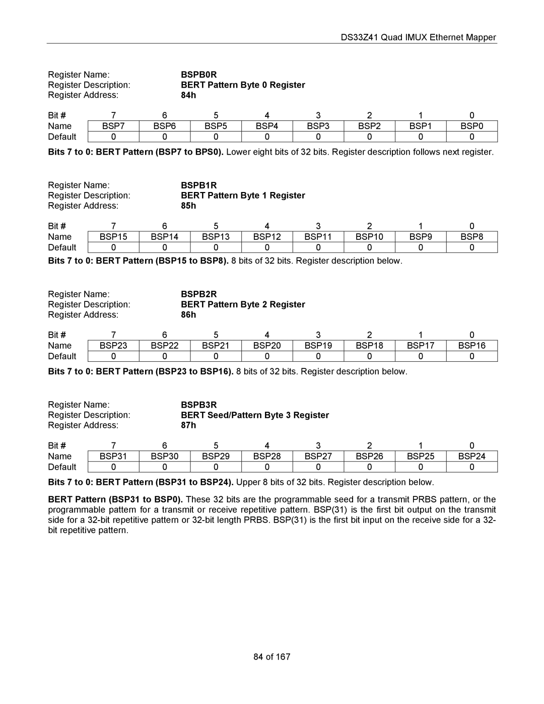
| BSPB0R |
|
|
|
|
|
| ||
Register Description: |
| BERT Pattern Byte 0 Register |
|
|
|
| ||||
Register Address: |
| 84h |
|
|
|
|
|
| ||
Bit # | 7 | 6 | 5 | 4 |
| 3 | 2 | 1 | 0 | |
Name | BSP7 | BSP6 |
| BSP5 | BSP4 |
| BSP3 | BSP2 | BSP1 | BSP0 |
Default | 0 | 0 |
| 0 | 0 |
| 0 | 0 | 0 | 0 |
Bits 7 to 0: BERT Pattern (BSP7 to BPS0). Lower eight bits of 32 bits. Register description follows next register.
Register Name: |
| BSPB1R |
|
|
|
|
| ||
Register Description: |
| BERT Pattern Byte 1 Register |
|
|
| ||||
Register Address: |
| 85h |
|
|
|
|
| ||
Bit # | 7 | 6 | 5 | 4 | 3 | 2 | 1 | 0 | |
Name | BSP15 | BSP14 |
| BSP13 | BSP12 | BSP11 | BSP10 | BSP9 | BSP8 |
Default | 0 | 0 |
| 0 | 0 | 0 | 0 | 0 | 0 |
Bits 7 to 0: BERT Pattern (BSP15 to BSP8). 8 bits of 32 bits. Register description below.
Register Name: |
| BSPB2R |
|
|
|
|
| ||
Register Description: |
| BERT Pattern Byte 2 Register |
|
|
| ||||
Register Address: |
| 86h |
|
|
|
|
| ||
Bit # | 7 | 6 | 5 | 4 | 3 | 2 | 1 | 0 | |
Name | BSP23 | BSP22 |
| BSP21 | BSP20 | BSP19 | BSP18 | BSP17 | BSP16 |
Default | 0 | 0 |
| 0 | 0 | 0 | 0 | 0 | 0 |
Bits 7 to 0: BERT Pattern (BSP23 to BSP16). 8 bits of 32 bits. Register description below. |
| ||||||||
Register Name: |
| BSPB3R |
|
|
|
|
| ||
Register Description: |
| BERT Seed/Pattern Byte 3 Register |
|
|
| ||||
Register Address: |
| 87h |
|
|
|
|
| ||
Bit # | 7 | 6 | 5 | 4 | 3 | 2 | 1 | 0 | |
Name | BSP31 | BSP30 |
| BSP29 | BSP28 | BSP27 | BSP26 | BSP25 | BSP24 |
Default | 0 | 0 |
| 0 | 0 | 0 | 0 | 0 | 0 |
Bits 7 to 0: BERT Pattern (BSP31 to BSP24). Upper 8 bits of 32 bits. Register description below.
BERT Pattern (BSP31 to BSP0). These 32 bits are the programmable seed for a transmit PRBS pattern, or the programmable pattern for a transmit or receive repetitive pattern. BSP(31) is the first bit output on the transmit side for a
84 of 167