DS33Z41 Quad IMUX Ethernet Mapper
Register Name: |
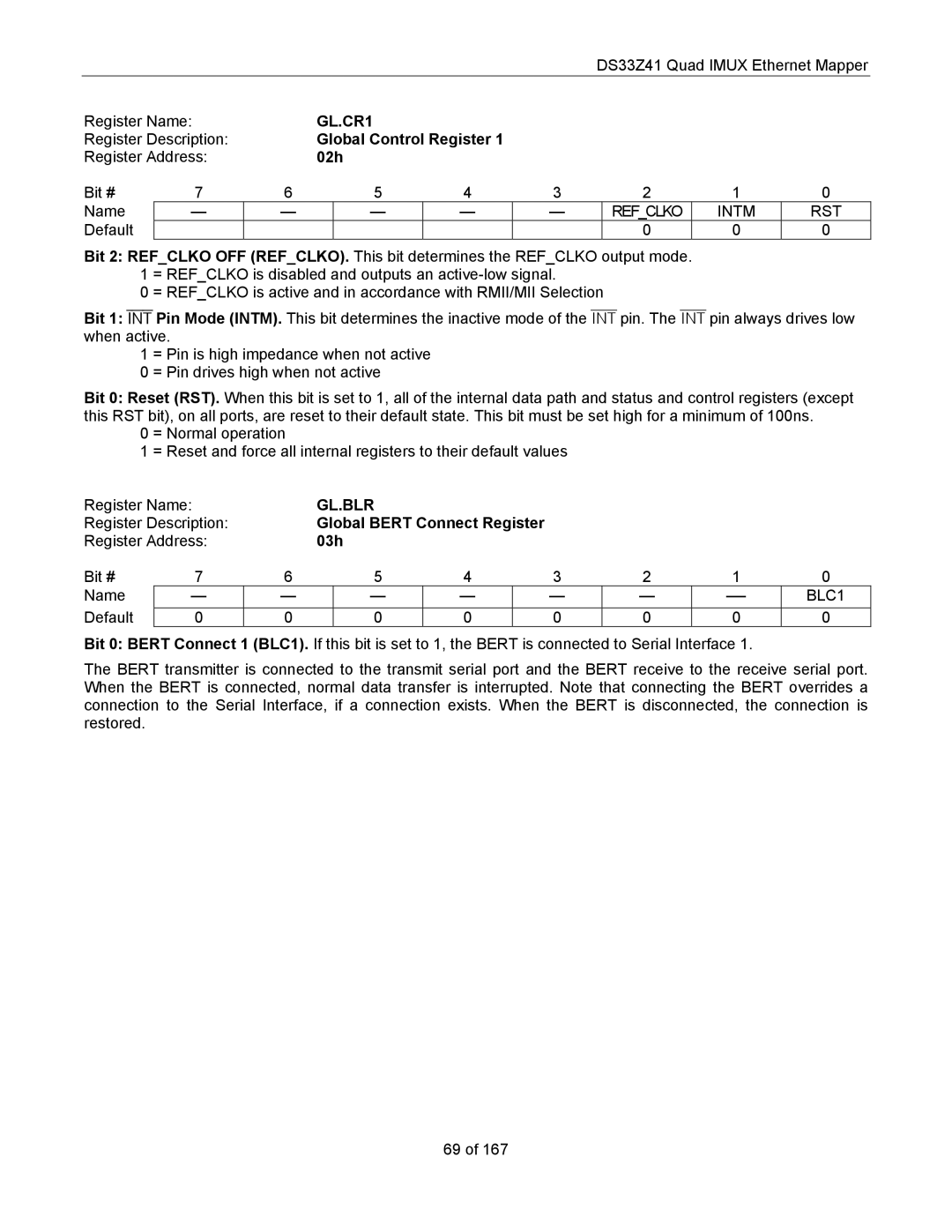
| GL.CR1 |
|
|
|
|
| ||
Register Description: |
| Global Control Register 1 |
|
|
|
| |||
Register Address: |
| 02h |
|
|
|
|
| ||
Bit # | 7 | 6 | 5 | 4 | 3 | 2 | 1 | 0 | |
Name | — | — |
| — | — | — | REF_CLKO | INTM | RST |
Default |
|
|
|
|
|
| 0 | 0 | 0 |
Bit 2: REF_CLKO OFF (REF_CLKO). This bit determines the REF_CLKO output mode. 1 = REF_CLKO is disabled and outputs an
0 = REF_CLKO is active and in accordance with RMII/MII Selection
Bit 1: INT Pin Mode (INTM). This bit determines the inactive mode of the INT pin. The INT pin always drives low when active.
1 = Pin is high impedance when not active
0 = Pin drives high when not active
Bit 0: Reset (RST). When this bit is set to 1, all of the internal data path and status and control registers (except this RST bit), on all ports, are reset to their default state. This bit must be set high for a minimum of 100ns.
0 = Normal operation
1 = Reset and force all internal registers to their default values
Register Name: |
| GL.BLR |
|
|
|
|
|
| ||
Register Description: |
| Global BERT Connect Register |
|
|
|
| ||||
Register Address: |
| 03h |
|
|
|
|
|
| ||
Bit # | 7 | 6 | 5 | 4 |
| 3 | 2 | 1 | 0 | |
Name | — | — |
| — | — |
| — | — | BLC1 | |
Default | 0 | 0 |
| 0 | 0 |
| 0 | 0 | 0 | 0 |
Bit 0: BERT Connect 1 (BLC1). If this bit is set to 1, the BERT is connected to Serial Interface 1.
The BERT transmitter is connected to the transmit serial port and the BERT receive to the receive serial port. When the BERT is connected, normal data transfer is interrupted. Note that connecting the BERT overrides a connection to the Serial Interface, if a connection exists. When the BERT is disconnected, the connection is restored.
69 of 167