|
|
|
| DS33Z41 Quad IMUX Ethernet Mapper |
|
|
|
|
|
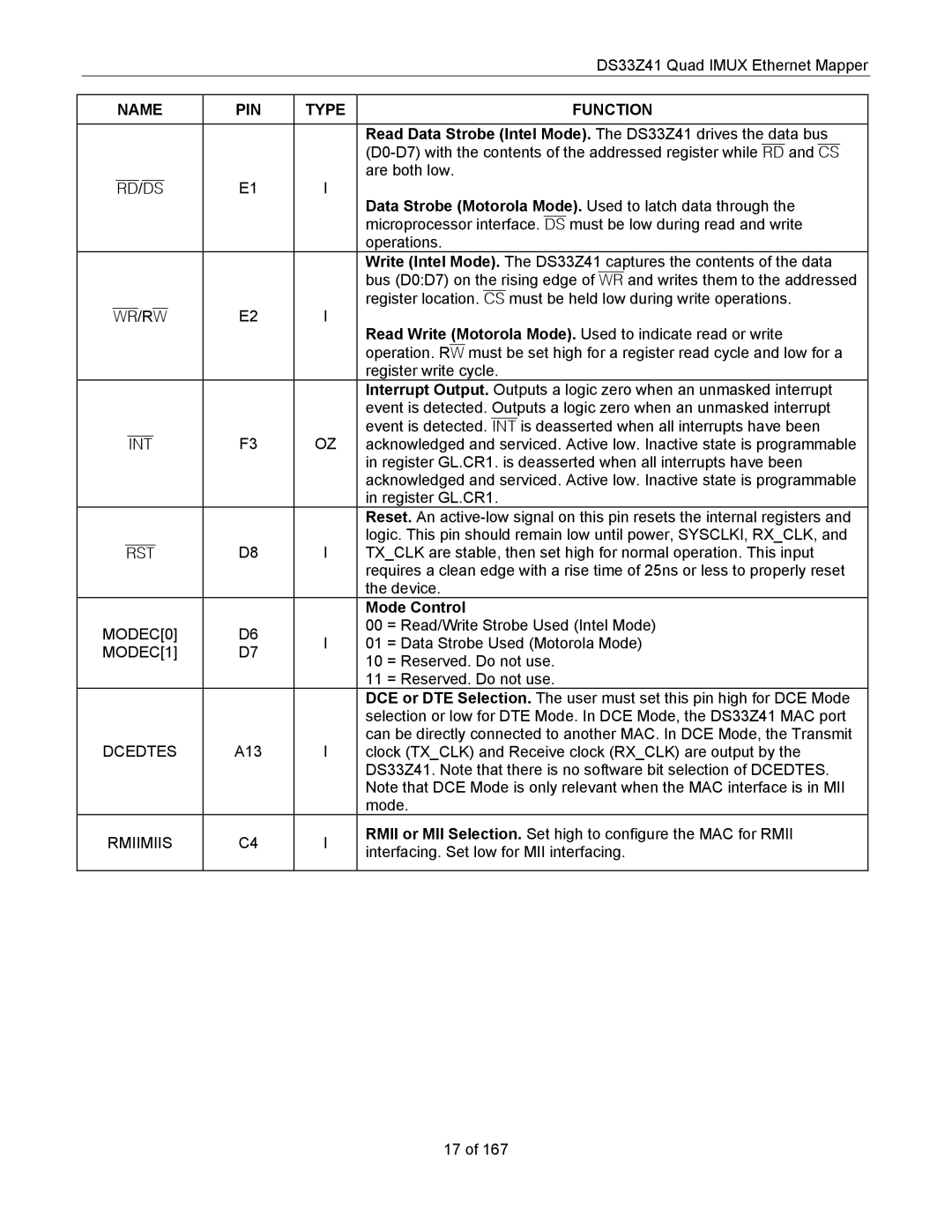
| NAME | PIN | TYPE | FUNCTION |
|
|
|
|
|
|
|
|
| Read Data Strobe (Intel Mode). The DS33Z41 drives the data bus |
|
|
|
| |
| RD/DS | E1 | I | are both low. |
| Data Strobe (Motorola Mode). Used to latch data through the | |||
|
|
|
| |
|
|
|
| microprocessor interface. DS must be low during read and write |
|
|
|
| operations. |
|
|
|
| Write (Intel Mode). The DS33Z41 captures the contents of the data |
|
|
|
| bus (D0:D7) on the rising edge of WR and writes them to the addressed |
| WR/RW | E2 | I | register location. CS must be held low during write operations. |
| Read Write (Motorola Mode). Used to indicate read or write | |||
|
|
|
| |
|
|
|
| operation. RW must be set high for a register read cycle and low for a |
|
|
|
| register write cycle. |
|
|
|
| Interrupt Output. Outputs a logic zero when an unmasked interrupt |
|
|
|
| event is detected. Outputs a logic zero when an unmasked interrupt |
|
| F3 | OZ | event is detected. INT is deasserted when all interrupts have been |
| INT | acknowledged and serviced. Active low. Inactive state is programmable | ||
|
|
|
| in register GL.CR1. is deasserted when all interrupts have been |
|
|
|
| acknowledged and serviced. Active low. Inactive state is programmable |
|
|
|
| in register GL.CR1. |
|
|
|
| Reset. An |
|
|
|
| logic. This pin should remain low until power, SYSCLKI, RX_CLK, and |
| RST | D8 | I | TX_CLK are stable, then set high for normal operation. This input |
|
|
|
| requires a clean edge with a rise time of 25ns or less to properly reset |
|
|
|
| the device. |
|
|
|
| Mode Control |
| MODEC[0] | D6 | I | 00 = Read/Write Strobe Used (Intel Mode) |
| 01 = Data Strobe Used (Motorola Mode) | |||
| MODEC[1] | D7 | ||
|
| 10 = Reserved. Do not use. | ||
|
|
|
| |
|
|
|
| 11 = Reserved. Do not use. |
|
|
|
| DCE or DTE Selection. The user must set this pin high for DCE Mode |
|
|
|
| selection or low for DTE Mode. In DCE Mode, the DS33Z41 MAC port |
| DCEDTES | A13 | I | can be directly connected to another MAC. In DCE Mode, the Transmit |
| clock (TX_CLK) and Receive clock (RX_CLK) are output by the | |||
|
|
|
| DS33Z41. Note that there is no software bit selection of DCEDTES. |
|
|
|
| Note that DCE Mode is only relevant when the MAC interface is in MII |
|
|
|
| mode. |
| RMIIMIIS | C4 | I | RMII or MII Selection. Set high to configure the MAC for RMII |
| interfacing. Set low for MII interfacing. | |||
|
|
|
| |
|
|
|
|
|
17 of 167