DS33Z41 Quad IMUX Ethernet Mapper
Register Name: |
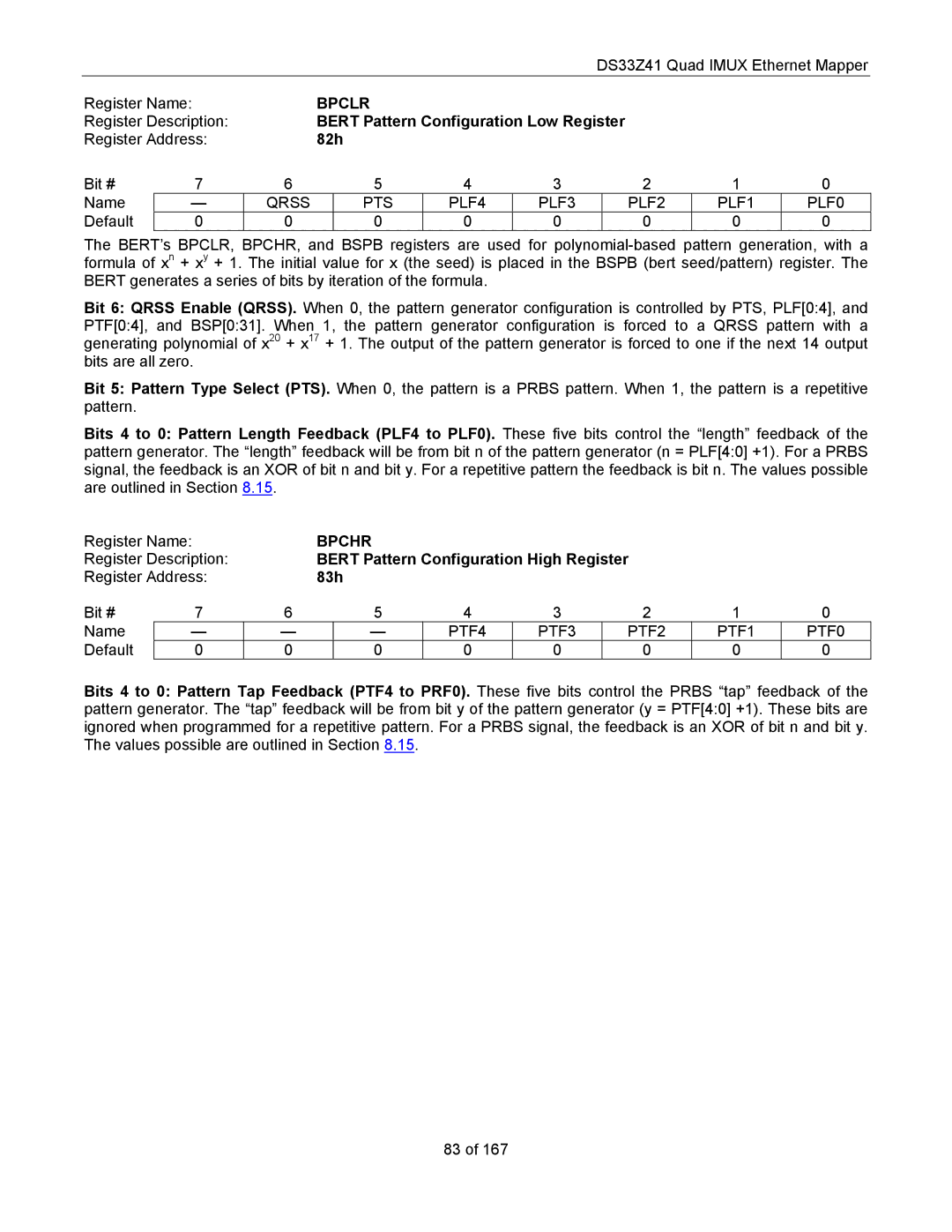
| BPCLR |
|
|
|
|
|
| ||
Register Description: |
| BERT Pattern Configuration Low Register |
|
|
| |||||
Register Address: |
| 82h |
|
|
|
|
|
| ||
Bit # | 7 | 6 | 5 | 4 | 3 |
| 2 | 1 | 0 | |
Name | — | QRSS |
| PTS | PLF4 | PLF3 |
| PLF2 | PLF1 | PLF0 |
Default | 0 | 0 |
| 0 | 0 | 0 |
| 0 | 0 | 0 |
The BERT’s BPCLR, BPCHR, and BSPB registers are used for
Bit 6: QRSS Enable (QRSS). When 0, the pattern generator configuration is controlled by PTS, PLF[0:4], and PTF[0:4], and BSP[0:31]. When 1, the pattern generator configuration is forced to a QRSS pattern with a generating polynomial of x20 + x17 + 1. The output of the pattern generator is forced to one if the next 14 output bits are all zero.
Bit 5: Pattern Type Select (PTS). When 0, the pattern is a PRBS pattern. When 1, the pattern is a repetitive pattern.
Bits 4 to 0: Pattern Length Feedback (PLF4 to PLF0). These five bits control the “length” feedback of the pattern generator. The “length” feedback will be from bit n of the pattern generator (n = PLF[4:0] +1). For a PRBS signal, the feedback is an XOR of bit n and bit y. For a repetitive pattern the feedback is bit n. The values possible are outlined in Section 8.15.
Register Name: |
| BPCHR |
|
|
|
|
| ||
Register Description: |
| BERT Pattern Configuration High Register |
|
| |||||
Register Address: |
| 83h |
|
|
|
|
| ||
Bit # | 7 | 6 | 5 | 4 | 3 | 2 | 1 | 0 | |
Name | — | — |
| — | PTF4 | PTF3 | PTF2 | PTF1 | PTF0 |
Default | 0 | 0 |
| 0 | 0 | 0 | 0 | 0 | 0 |
Bits 4 to 0: Pattern Tap Feedback (PTF4 to PRF0). These five bits control the PRBS “tap” feedback of the pattern generator. The “tap” feedback will be from bit y of the pattern generator (y = PTF[4:0] +1). These bits are ignored when programmed for a repetitive pattern. For a PRBS signal, the feedback is an XOR of bit n and bit y. The values possible are outlined in Section 8.15.
83 of 167