DS33Z41 Quad IMUX Ethernet Mapper
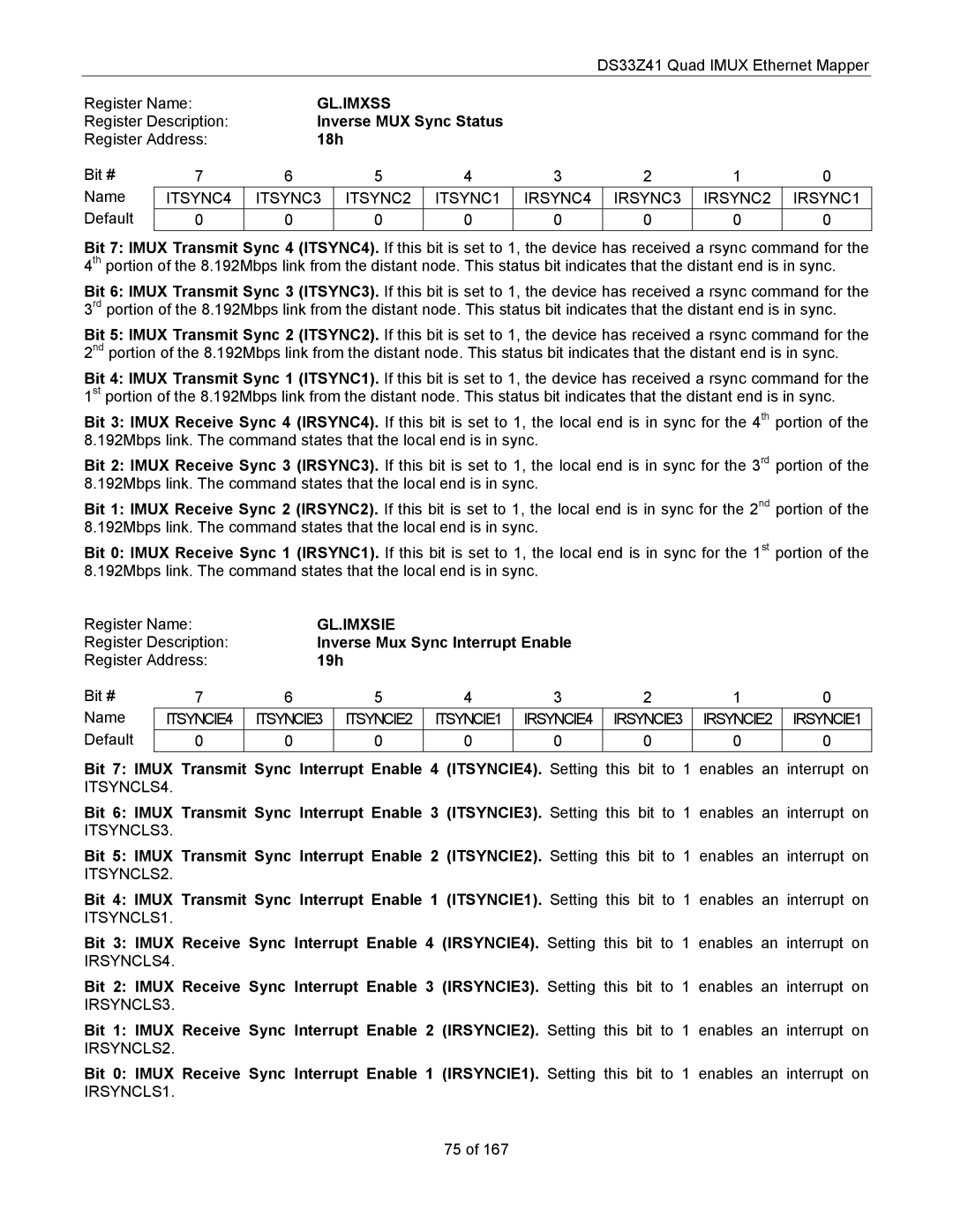
Register Name: | GL.IMXSS |
|
|
|
|
| |||
Register Description: | Inverse MUX Sync Status |
|
|
|
| ||||
Register Address: | 18h |
|
|
|
|
|
| ||
Bit # | 7 | 6 |
| 5 | 4 | 3 | 2 | 1 | 0 |
Name | ITSYNC4 | ITSYNC3 |
| ITSYNC2 | ITSYNC1 | IRSYNC4 | IRSYNC3 | IRSYNC2 | IRSYNC1 |
Default | 0 | 0 |
| 0 | 0 | 0 | 0 | 0 | 0 |
Bit 7: IMUX Transmit Sync 4 (ITSYNC4). If this bit is set to 1, the device has received a rsync command for the 4th portion of the 8.192Mbps link from the distant node. This status bit indicates that the distant end is in sync.
Bit 6: IMUX Transmit Sync 3 (ITSYNC3). If this bit is set to 1, the device has received a rsync command for the 3rd portion of the 8.192Mbps link from the distant node. This status bit indicates that the distant end is in sync.
Bit 5: IMUX Transmit Sync 2 (ITSYNC2). If this bit is set to 1, the device has received a rsync command for the 2nd portion of the 8.192Mbps link from the distant node. This status bit indicates that the distant end is in sync.
Bit 4: IMUX Transmit Sync 1 (ITSYNC1). If this bit is set to 1, the device has received a rsync command for the 1st portion of the 8.192Mbps link from the distant node. This status bit indicates that the distant end is in sync.
Bit 3: IMUX Receive Sync 4 (IRSYNC4). If this bit is set to 1, the local end is in sync for the 4th portion of the 8.192Mbps link. The command states that the local end is in sync.
Bit 2: IMUX Receive Sync 3 (IRSYNC3). If this bit is set to 1, the local end is in sync for the 3rd portion of the 8.192Mbps link. The command states that the local end is in sync.
Bit 1: IMUX Receive Sync 2 (IRSYNC2). If this bit is set to 1, the local end is in sync for the 2nd portion of the 8.192Mbps link. The command states that the local end is in sync.
Bit 0: IMUX Receive Sync 1 (IRSYNC1). If this bit is set to 1, the local end is in sync for the 1st portion of the 8.192Mbps link. The command states that the local end is in sync.
Register Name: | GL.IMXSIE |
|
|
|
|
| |||
Register Description: | Inverse Mux Sync Interrupt Enable |
|
|
| |||||
Register Address: | 19h |
|
|
|
|
|
| ||
Bit # | 7 | 6 |
| 5 | 4 | 3 | 2 | 1 | 0 |
Name | ITSYNCIE4 | ITSYNCIE3 |
| ITSYNCIE2 | ITSYNCIE1 | IRSYNCIE4 | IRSYNCIE3 | IRSYNCIE2 | IRSYNCIE1 |
Default | 0 | 0 |
| 0 | 0 | 0 | 0 | 0 | 0 |
Bit 7: IMUX Transmit Sync Interrupt Enable 4 (ITSYNCIE4). Setting this bit to 1 enables an interrupt on ITSYNCLS4.
Bit 6: IMUX Transmit Sync Interrupt Enable 3 (ITSYNCIE3). Setting this bit to 1 enables an interrupt on ITSYNCLS3.
Bit 5: IMUX Transmit Sync Interrupt Enable 2 (ITSYNCIE2). Setting this bit to 1 enables an interrupt on ITSYNCLS2.
Bit 4: IMUX Transmit Sync Interrupt Enable 1 (ITSYNCIE1). Setting this bit to 1 enables an interrupt on ITSYNCLS1.
Bit 3: IMUX Receive Sync Interrupt Enable 4 (IRSYNCIE4). Setting this bit to 1 enables an interrupt on IRSYNCLS4.
Bit 2: IMUX Receive Sync Interrupt Enable 3 (IRSYNCIE3). Setting this bit to 1 enables an interrupt on IRSYNCLS3.
Bit 1: IMUX Receive Sync Interrupt Enable 2 (IRSYNCIE2). Setting this bit to 1 enables an interrupt on IRSYNCLS2.
Bit 0: IMUX Receive Sync Interrupt Enable 1 (IRSYNCIE1). Setting this bit to 1 enables an interrupt on IRSYNCLS1.
75 of 167