HOME AUTOMATION
The Control Panel can be used to control lights and home applicances with a Control Module, (Control Module is sold separately). Garage door opener can be controlled with a Garage Door Receiver (sold separately). The Control Panel can control up to 5 Control Modules / Garage Door Receivers.
There are 3 ways to control these modules / receivers:
1. Using the keypad on the control panel to operate these modules / receivers manually
2. Calling in away from home using a touch tone phone (Refer to “Remote Operation by Telephone”)
Door open | Lights |
| on |
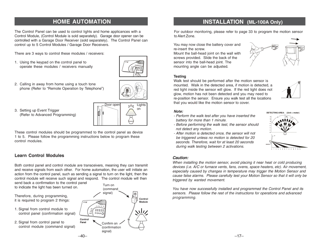
INSTALLATION (ML-100A Only)
For outdoor monitoring, please refer to page 33 to program the motion sensor to Alert Zone.
You may now close the battery cover and
Mount the
Testing
Walk test should be performed after the motion sensor is mounted. Walk in the detected area, if motion is detected, a red light inside the sensor will glow. If the red light does not glow, motion has not been detected and you may need to
3. Setting up Event Trigger |
(Refer to Advanced Programming) |
These control modules should be programmed to the control panel as device 1 to 5. Please follow the programming instructions below to program these control modules.
Note:
-Perform the walk test after you have inserted the battery for more than 1 minute.
-Before performing the walk test, the sensor should not detect any motion.
-After motion is detected once, the sensor will not be triggered unless no motion is detected for 20 seconds. Therefore, wait for at least 20 seconds during walk testing between 2 activations.
DETECTING AREA: (Unit = meter)
14 | 55° | 1.2M |
| 55° | |
12 |
| 11° |
10 |
|
|
8 |
|
|
6 |
| 27° |
| 22° | 22° |
4 |
|
|
2 |
|
|
M |
|
|
| 12° |
|
SENSOR
0 | 1 | 2 | 3 | 4 | 5 | 6 | 7 | 8 | 9 | 10 | 11 | 12 | 13 |
Learn Control Modules
Both control panel and control module are transceivers, meaning they can transmit and receive signals from each other. For home automation, the user will initiate an action from the control panel, such as sending a signal to turn on the light, then the control module will receive such signal and respond. The control module will then send back a confirmation to the control panel
to indicate the light has been turned on.
Caution:
When installing the motion sensor, avoid placing it near heat or cold producing devices (i.e. A/C or furnace vents, fans, ovens, space heaters, etc). Air movement, especially caused by changes in temperature may trigger the Motion Sensor and cause false alarms. Please carefully test your Motion Sensor so that it will only be triggered by wanted movement.
You have now successfully installed and programmed the Control Panel and its sensors. Please follow the rest of the instructions for operations and advanced
Therefore, during programming, it is required to program 2 things:
1.Signal from control module to control panel (confirmation signal)
2.Signal from control panel to control module (command signal)
PWR
ARM
PROG
LO BATT
Control Panel
Control
Module
1 | 2 | 3 | 4 | 5 |
1 | 2 | 3 | 4 |
|
| 5 | |||
6 | 7 | 8 | 9 |
|
| 0 | |||
ARM | STATUS | MUTE |
|
|
Confirm on (confirmation signal)
programming.