![]()
![]()
![]() ®
®
ACCESSORIES
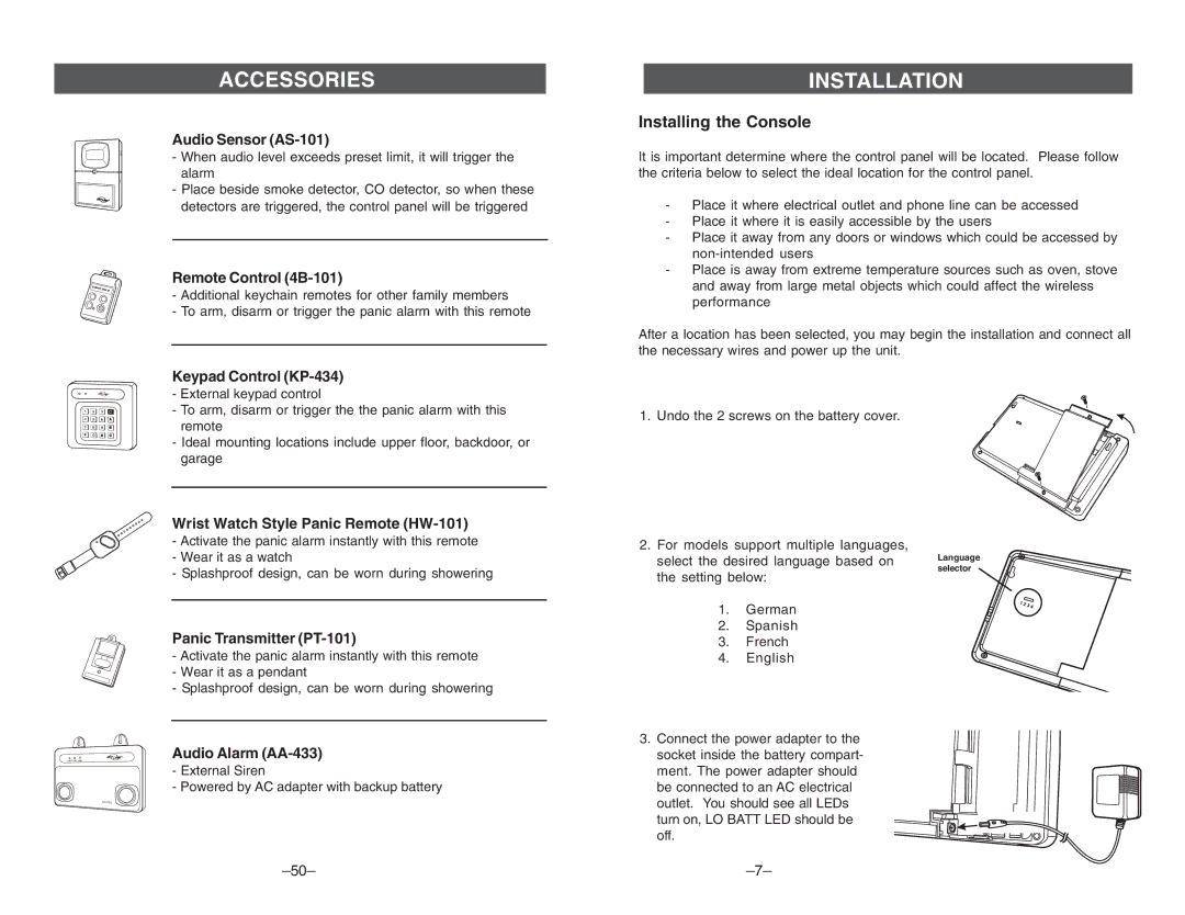
Audio Sensor (AS-101)
-When audio level exceeds preset limit, it will trigger the alarm
-Place beside smoke detector, CO detector, so when these detectors are triggered, the control panel will be triggered
Remote Control (4B-101)
-Additional keychain remotes for other family members
-To arm, disarm or trigger the panic alarm with this remote
Keypad Control (KP-434)
-External keypad control
-To arm, disarm or trigger the the panic alarm with this remote
-Ideal mounting locations include upper floor, backdoor, or garage
Wrist Watch Style Panic Remote (HW-101)
-Activate the panic alarm instantly with this remote
-Wear it as a watch
-Splashproof design, can be worn during showering
Panic Transmitter (PT-101)
-Activate the panic alarm instantly with this remote
-Wear it as a pendant
-Splashproof design, can be worn during showering
Audio Alarm
-External Siren
-Powered by AC adapter with backup battery
INSTALLATION
Installing the Console
It is important determine where the control panel will be located. Please follow the criteria below to select the ideal location for the control panel.
-Place it where electrical outlet and phone line can be accessed
-Place it where it is easily accessible by the users
-Place it away from any doors or windows which could be accessed by
-Place is away from extreme temperature sources such as oven, stove and away from large metal objects which could affect the wireless performance
After a location has been selected, you may begin the installation and connect all the necessary wires and power up the unit.
1. Undo the 2 screws on the battery cover.
2. For models support multiple languages,
select the desired language based on Language
selector
the setting below:
1. German
2.Spanish
3.French
4.English
3.Connect the power adapter to the socket inside the battery compart- ment. The power adapter should
be connected to an AC electrical outlet. You should see all LEDs turn on, LO BATT LED should be off.