Subnet 0 | 207.168.12.1 – 207.168.12.62 |
Subnet 1 | 207.168.12.65 – 207.168.12.126 |
Subnet 2 | 207.168.12.129 – 207.168.12.190 |
Subnet 3 | 207.168.12.193 – 207.168.12.254 |
As shown, the Ethernet segment makes up subnet 0 and the
Workstations on the Ethernet LAN are configured with their Default Gateway set to 207.168.12.1. Workstations and the server on the
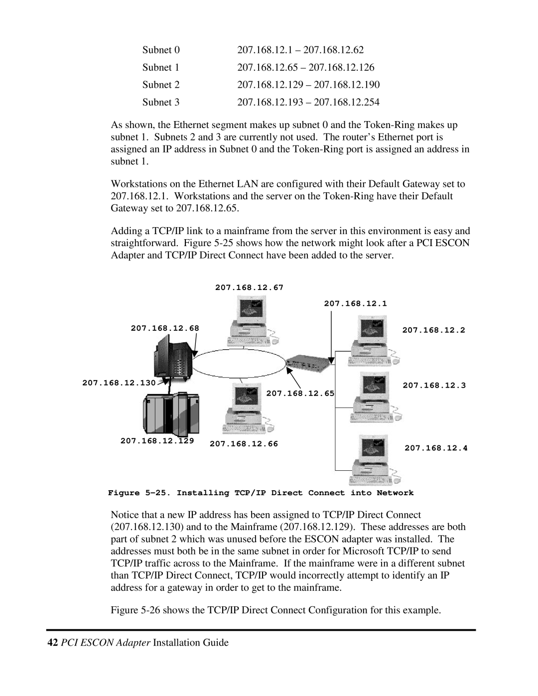
Adding a TCP/IP link to a mainframe from the server in this environment is easy and straightforward. Figure
| 207.168.12.67 |
|
| 207.168.12.1 | |
207.168.12.68 |
| |
| 207.168.12.2 | |
|
|
|
207.168.12.130 |
| 207.168.12.3 |
| 207.168.12.65 | |
|
| |
207.168.12.129 | 207.168.12.66 | 207.168.12.4 |
| ||
|
| |
Figure | ||
Notice that a new IP address has been assigned to TCP/IP Direct Connect (207.168.12.130) and to the Mainframe (207.168.12.129). These addresses are both part of subnet 2 which was unused before the ESCON adapter was installed. The addresses must both be in the same subnet in order for Microsoft TCP/IP to send TCP/IP traffic across to the Mainframe. If the mainframe were in a different subnet than TCP/IP Direct Connect, TCP/IP would incorrectly attempt to identify an IP address for a gateway in order to get to the mainframe.
