Chapter 2 - Installation
Voice/Fax Cable Connections
NOTE: The E&M, FXS, and Ethernet ports are not designed to be connected to a Public Telecommunication Network.
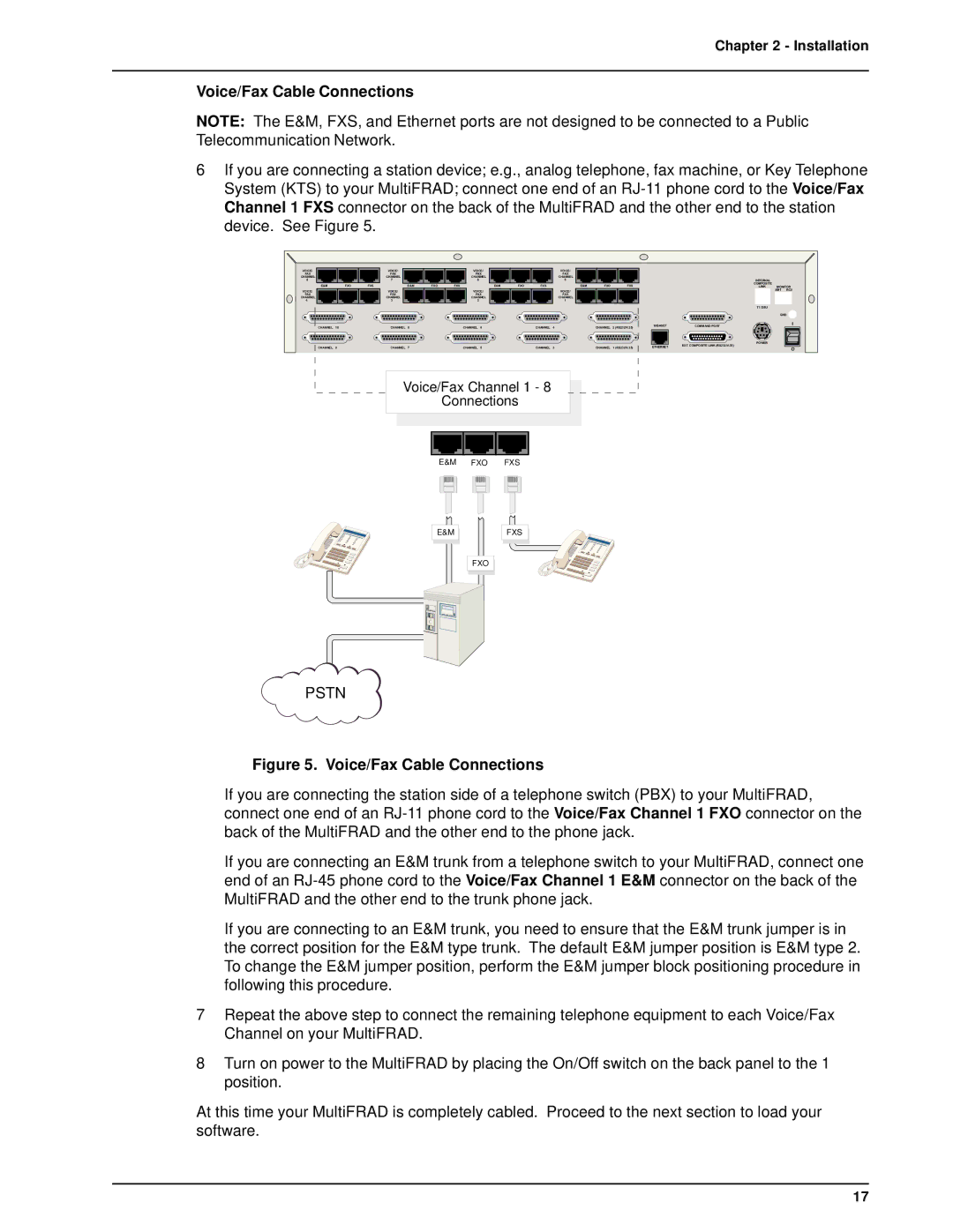
6If you are connecting a station device; e.g., analog telephone, fax machine, or Key Telephone System (KTS) to your MultiFRAD; connect one end of an
VOICE/ |
|
| VOICE/ |
|
| VOICE/ |
|
|
|
| VOICE/ |
|
| |
FAX |
|
| FAX |
|
| FAX |
|
|
|
| FAX |
|
| |
CHANNEL |
|
| CHANNEL |
|
| CHANNEL |
|
|
|
| CHANNEL |
|
| |
8 |
|
| 7 |
|
| 6 |
|
|
|
|
| 5 |
|
|
E&M | FXO | FXS |
| E&M | FXO | FXS |
| E&M | FXO | FXS |
| E&M | FXO | FXS |
VOICE/ |
|
| VOICE/ |
|
| VOICE/ |
|
|
|
| VOICE/ |
|
| |
FAX |
|
| FAX |
|
| FAX |
|
|
|
| FAX |
|
| |
CHANNEL |
|
| CHANNEL |
|
| CHANNEL |
|
|
|
| CHANNEL |
|
| |
4 |
|
| 3 |
|
| 2 |
|
|
|
|
| 1 |
|
|
CHANNEL | 10 |
| CHANNEL | 8 |
| CHANNEL | 6 |
|
| CHANNEL | 4 |
| CHANNEL | 2 (RS232/V.35) |
CHANNEL | 9 |
| CHANNEL | 7 |
| CHANNEL | 5 |
|
| CHANNEL | 3 |
| CHANNEL | 1 (RS232/V.35) |
10BASET | COMMAND PORT |
ETHERNET | EXT. COMPOSITE LINK (RS232/V.35) |
INTERNAL
COMPOSITE
LINK MONITOR XMT RCV
T1 DSU
GND
I
POWER![]() O
O
Voice/Fax Channel 1 - 8
Connections
E&M FXO FXS
E&M |
FXO |
FXS
PSTN
Figure 5. Voice/Fax Cable Connections
If you are connecting the station side of a telephone switch (PBX) to your MultiFRAD, connect one end of an
If you are connecting an E&M trunk from a telephone switch to your MultiFRAD, connect one end of an
If you are connecting to an E&M trunk, you need to ensure that the E&M trunk jumper is in the correct position for the E&M type trunk. The default E&M jumper position is E&M type 2. To change the E&M jumper position, perform the E&M jumper block positioning procedure in following this procedure.
7Repeat the above step to connect the remaining telephone equipment to each Voice/Fax Channel on your MultiFRAD.
8Turn on power to the MultiFRAD by placing the On/Off switch on the back panel to the 1 position.
At this time your MultiFRAD is completely cabled. Proceed to the next section to load your software.
17