Chapter 1 - Introduction and Description
Back Panel Description
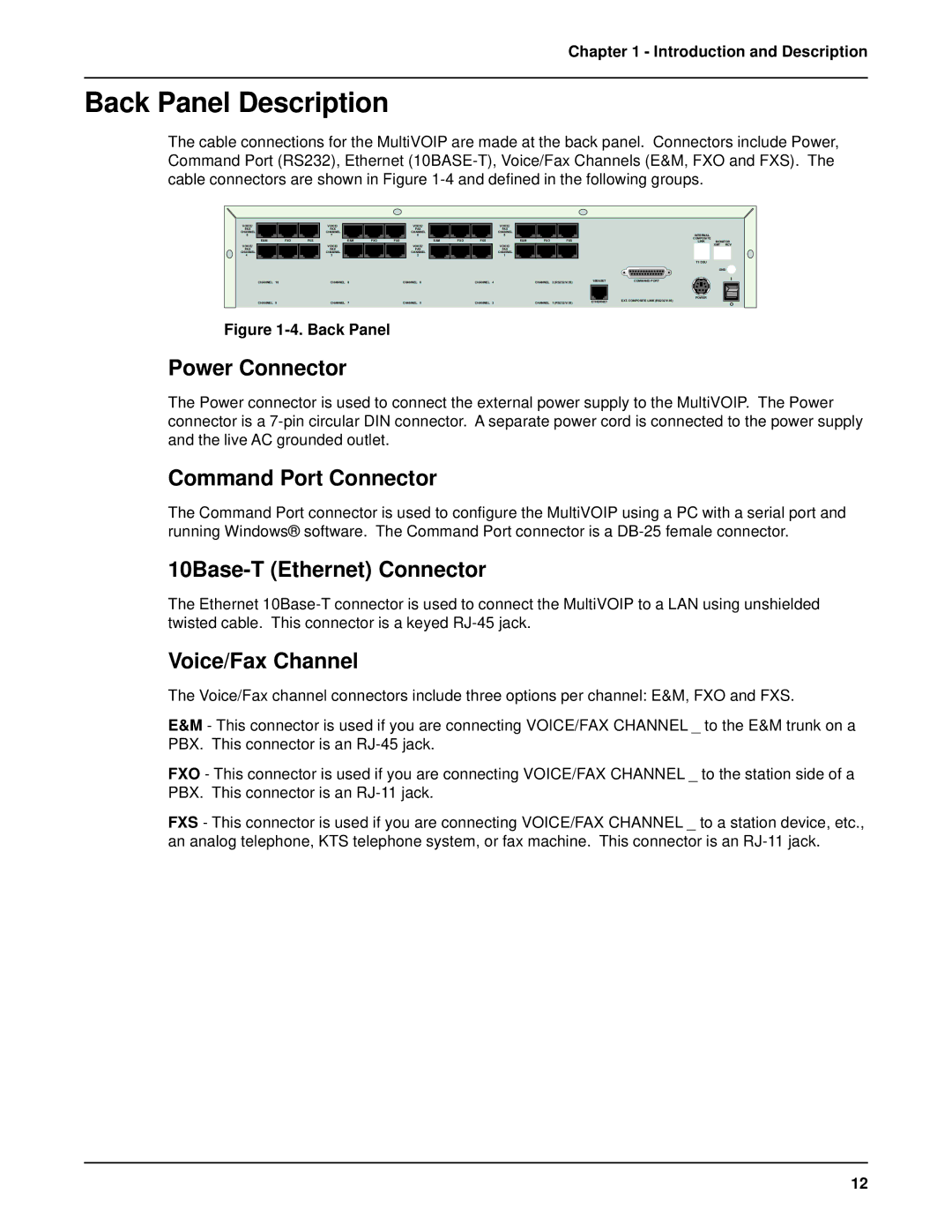
The cable connections for the MultiVOIP are made at the back panel. Connectors include Power, Command Port (RS232), Ethernet
VOICE/ |
|
| VOICE/ |
|
| VOICE/ |
|
|
|
| VOICE/ |
|
| |
FAX |
|
| FAX |
|
| FAX |
|
|
|
| FAX |
|
| |
CHANNEL |
|
| CHANNEL |
|
| CHANNEL |
|
|
|
| CHANNEL |
|
| |
8 |
|
| 7 |
|
| 6 |
|
|
|
|
| 5 |
|
|
E&M | FXO | FXS |
| E&M | FXO | FXS |
| E&M | FXO | FXS |
| E&M | FXO | FXS |
VOICE/ |
|
| VOICE/ |
|
| VOICE/ |
|
|
|
| VOICE/ |
|
| |
FAX |
|
| FAX |
|
| FAX |
|
|
|
| FAX |
|
| |
CHANNEL |
|
| CHANNEL |
|
| CHANNEL |
|
|
|
| CHANNEL |
|
| |
4 |
|
| 3 |
|
| 2 |
|
|
|
|
| 1 |
|
|
CHANNEL | 10 |
| CHANNEL | 8 |
| CHANNEL | 6 |
|
| CHANNEL | 4 |
| CHANNEL | 2 (RS232/V.35) |
CHANNEL | 9 |
| CHANNEL | 7 |
| CHANNEL | 5 |
|
| CHANNEL | 3 |
| CHANNEL | 1 (RS232/V.35) |
Figure 1-4. Back Panel
| INTERNAL |
|
|
| COMPOSITE |
|
|
| LINK | MONITOR | |
|
| XMT | RCV |
| T1 DSU |
|
|
|
| GND | |
10BASET | COMMAND PORT |
| I |
| POWER |
|
|
ETHERNET | EXT. COMPOSITE LINK (RS232/V.35) |
| O |
|
|
| |
Power Connector
The Power connector is used to connect the external power supply to the MultiVOIP. The Power connector is a
Command Port Connector
The Command Port connector is used to configure the MultiVOIP using a PC with a serial port and running Windows® software. The Command Port connector is a
10Base-T (Ethernet) Connector
The Ethernet
Voice/Fax Channel
The Voice/Fax channel connectors include three options per channel: E&M, FXO and FXS.
E&M - This connector is used if you are connecting VOICE/FAX CHANNEL _ to the E&M trunk on a PBX. This connector is an
FXO - This connector is used if you are connecting VOICE/FAX CHANNEL _ to the station side of a PBX. This connector is an
FXS - This connector is used if you are connecting VOICE/FAX CHANNEL _ to a station device, etc., an analog telephone, KTS telephone system, or fax machine. This connector is an
12