Chapter 2 - Installation
E&M Jumper Block Positioning Procedure
A jumper block exists for each voice/fax channel. The jumper block is to the right of each set of channel jacks. The jumper block contains
1.Ensure that power is removed from the MultiVOIP
2.Remove the front panel by loosening the two Phillips
3.Remove the screws at the back of the chassis, then slide the top cover back off the chassis to expose the rear panel.
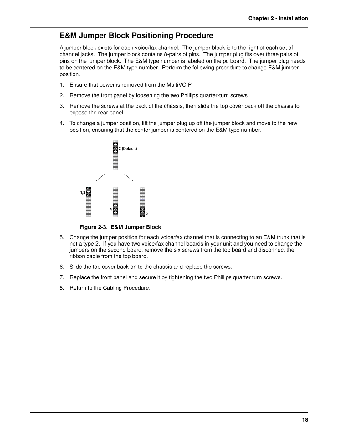
4.To change a jumper position, lift the jumper plug up off the jumper block and move to the new position, ensuring that the center jumper is centered on the E&M type number.
2 (Default) |
1,3 |
4 |
5 |
Figure 2-3. E&M Jumper Block
5.Change the jumper position for each voice/fax channel that is connecting to an E&M trunk that is not a type 2. If you have two voice/fax channel boards in your unit and you need to change the jumpers on the second board, remove the six screws from the top board and disconnect the ribbon cable from the top board.
6.Slide the top cover back on to the chassis and replace the screws.
7.Replace the front panel and secure it by tightening the two Phillips quarter turn screws.
8.Return to the Cabling Procedure.
18