Chapter 2 - Installation
Cabling Procedure
Cabling involves connecting the host MultiVOIP to your LAN and telephone equipment.
1.If you are connecting any Voice/Fax Channel to an E&M trunk other than type 2, perform the E&M Jumper Block Positioning procedure which appears later in this chapter before connecting power to the unit.
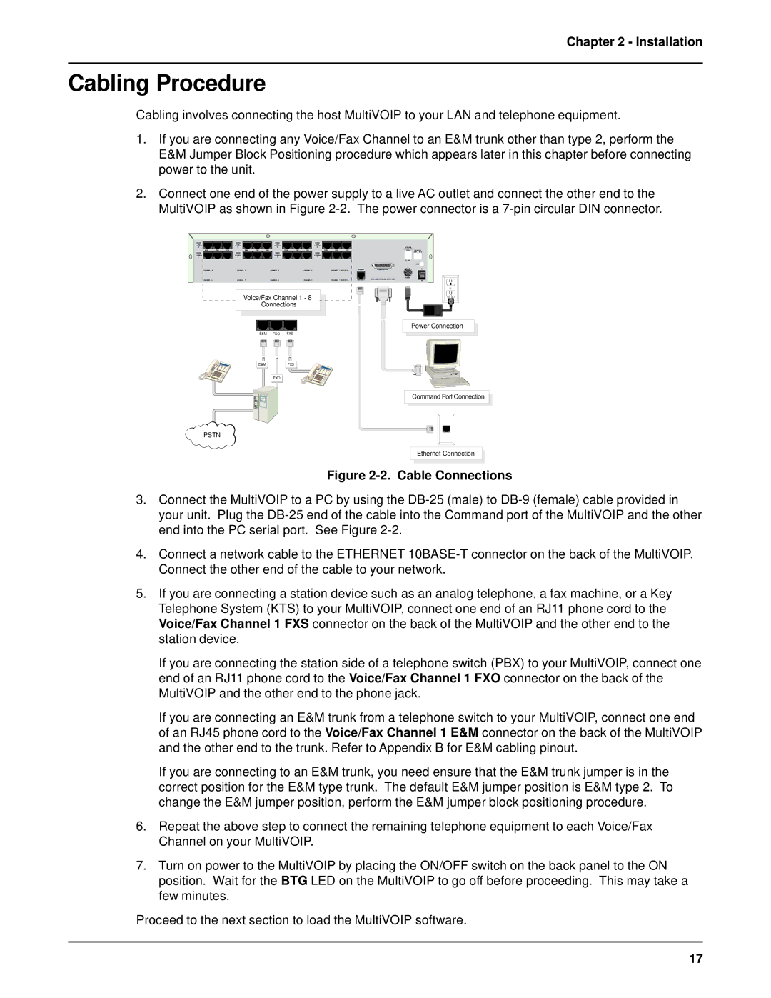
2.Connect one end of the power supply to a live AC outlet and connect the other end to the MultiVOIP as shown in Figure
VOICE/ |
|
| VOICE/ |
|
| VOICE/ |
|
|
|
| VOICE/ |
|
| |
FAX |
|
| FAX |
|
| FAX |
|
|
|
| FAX |
|
| |
CHANNEL |
|
| CHANNEL |
|
| CHANNEL |
|
|
|
| CHANNEL |
|
| |
8 |
|
| 7 |
|
| 6 |
|
|
|
|
| 5 |
|
|
E&M | FXO | FXS |
| E&M | FXO | FXS |
| E&M | FXO | FXS |
| E&M | FXO | FXS |
VOICE/ |
|
| VOICE/ |
|
| VOICE/ |
|
|
|
| VOICE/ |
|
| |
FAX |
|
| FAX |
|
| FAX |
|
|
|
| FAX |
|
| |
CHANNEL |
|
| CHANNEL |
|
| CHANNEL |
|
|
|
| CHANNEL |
|
| |
4 |
|
| 3 |
|
| 2 |
|
|
|
|
| 1 |
|
|
CHANNEL | 10 |
| CHANNEL | 8 |
| CHANNEL | 6 |
|
| CHANNEL | 4 |
| CHANNEL | 2 (RS232/V.35) |
CHANNEL | 9 |
| CHANNEL | 7 |
| CHANNEL | 5 |
|
| CHANNEL | 3 |
| CHANNEL | 1 (RS232/V.35) |
10BASET |
| COMMAND PORT | |||||
|
|
| EXT. COMPOSITE LINK (RS232/V.35) | ||||
ETHERNET |
| ||||||
|
|
|
|
|
|
|
|
|
|
|
|
|
|
|
|
|
|
|
|
|
|
|
|
INTERNAL
COMPOSITE
LINK MONITOR XMT RCV
T1 DSU
GND
I
POWER ![]() O
O
Voice/Fax Channel 1 - 8
Connections
E&M FXO FXS
Power Connection
E&M |
FXO |
FXS
Command Port Connection
PSTN
Ethernet Connection
Figure 2-2. Cable Connections
3.Connect the MultiVOIP to a PC by using the
4.Connect a network cable to the ETHERNET
5.If you are connecting a station device such as an analog telephone, a fax machine, or a Key Telephone System (KTS) to your MultiVOIP, connect one end of an RJ11 phone cord to the Voice/Fax Channel 1 FXS connector on the back of the MultiVOIP and the other end to the station device.
If you are connecting the station side of a telephone switch (PBX) to your MultiVOIP, connect one end of an RJ11 phone cord to the Voice/Fax Channel 1 FXO connector on the back of the MultiVOIP and the other end to the phone jack.
If you are connecting an E&M trunk from a telephone switch to your MultiVOIP, connect one end of an RJ45 phone cord to the Voice/Fax Channel 1 E&M connector on the back of the MultiVOIP and the other end to the trunk. Refer to Appendix B for E&M cabling pinout.
If you are connecting to an E&M trunk, you need ensure that the E&M trunk jumper is in the correct position for the E&M type trunk. The default E&M jumper position is E&M type 2. To change the E&M jumper position, perform the E&M jumper block positioning procedure.
6.Repeat the above step to connect the remaining telephone equipment to each Voice/Fax Channel on your MultiVOIP.
7.Turn on power to the MultiVOIP by placing the ON/OFF switch on the back panel to the ON position. Wait for the BTG LED on the MultiVOIP to go off before proceeding. This may take a few minutes.
Proceed to the next section to load the MultiVOIP software.
17