Chapter 1 - Introduction and Description
MultiVOIP Application
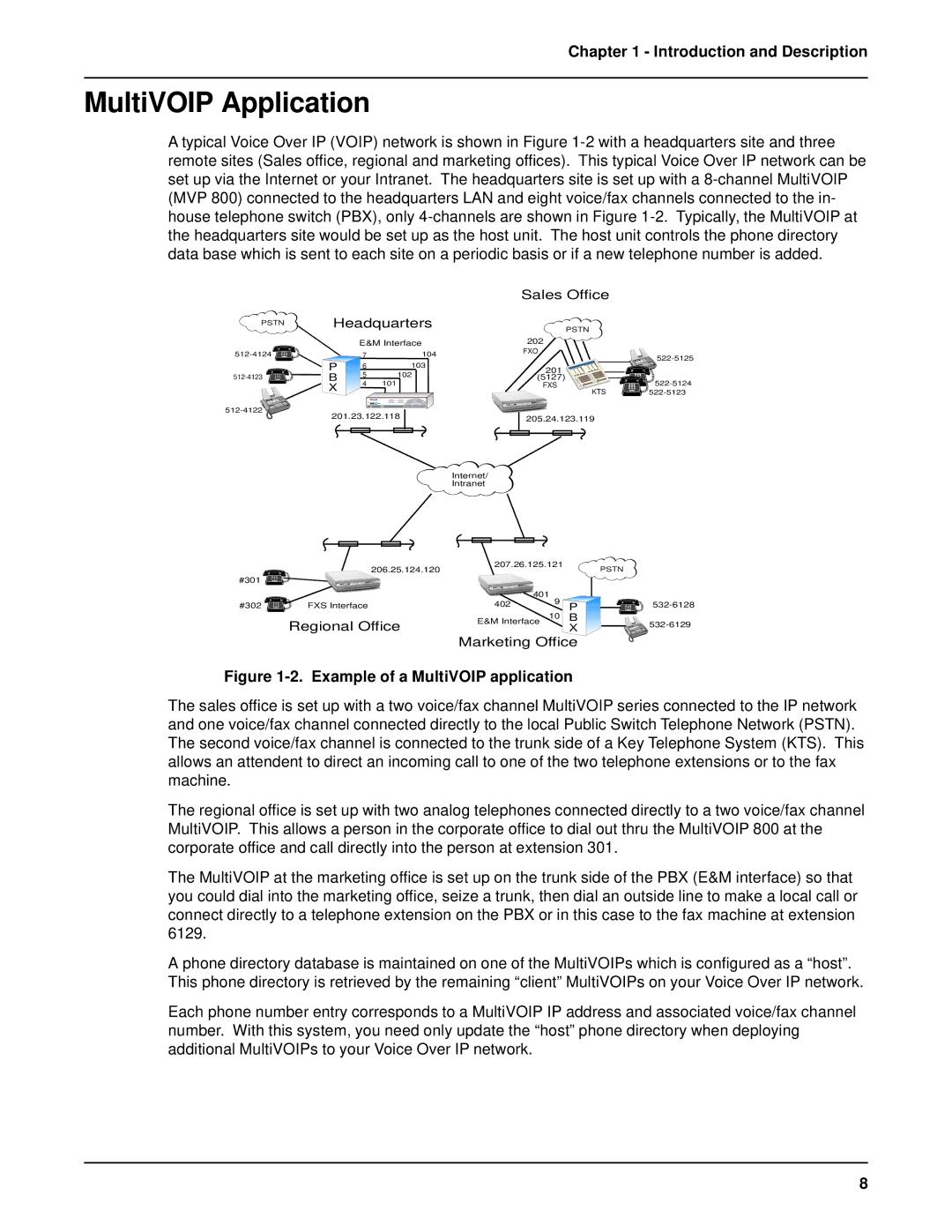
A typical Voice Over IP (VOIP) network is shown in Figure
PSTN | Headquarters | |||
|
| E&M Interface | ||
| 7 | 104 | ||
| P | 6 | 103 | |
B | 5 | 102 | ||
4 | 101 | |||
| X | |||
|
|
| ||
![]()
201.23.122.118
Internet/
Intranet
Sales Office
PSTN
202
FXO
| |
201 |
|
(5127) | |
FXS | |
KTS |
205.24.123.119
| 206.25.124.120 | 207.26.125.121 |
| PSTN | |
|
|
|
| ||
#301 |
|
|
|
|
|
|
|
| 401 |
|
|
#302 | FXS Interface | 402 | 9 | P | |
|
|
| 10 | B |
|
| Regional Office | E&M Interface | X | ||
|
|
| |||
Marketing Office
Figure 1-2. Example of a MultiVOIP application
The sales office is set up with a two voice/fax channel MultiVOIP series connected to the IP network and one voice/fax channel connected directly to the local Public Switch Telephone Network (PSTN). The second voice/fax channel is connected to the trunk side of a Key Telephone System (KTS). This allows an attendent to direct an incoming call to one of the two telephone extensions or to the fax machine.
The regional office is set up with two analog telephones connected directly to a two voice/fax channel MultiVOIP. This allows a person in the corporate office to dial out thru the MultiVOIP 800 at the corporate office and call directly into the person at extension 301.
The MultiVOIP at the marketing office is set up on the trunk side of the PBX (E&M interface) so that you could dial into the marketing office, seize a trunk, then dial an outside line to make a local call or connect directly to a telephone extension on the PBX or in this case to the fax machine at extension 6129.
A phone directory database is maintained on one of the MultiVOIPs which is configured as a “host”. This phone directory is retrieved by the remaining “client” MultiVOIPs on your Voice Over IP network.
Each phone number entry corresponds to a MultiVOIP IP address and associated voice/fax channel number. With this system, you need only update the “host” phone directory when deploying additional MultiVOIPs to your Voice Over IP network.
8