MultiVOIP FX User Guide | Mechanical Installation & Cabling |
|
|
5.Repeat step 4 to connect the remaining telephone equipment to each channel on your MultiVOIP. Although a MultiVOIP’s channels are often all configured identically, each channel is individually configurable. So, for example, some channels of a MultiVOIP might use the FXO interface and others the FXS.
6.Ensure that the unit is properly connected to earth ground by verifying that it is reliably grounded when mounted within a rack.
This can be accomplished by connecting a grounding wire between the chassis grounding screw (see Figure
7.Turn on power to the MultiVOIP by placing the ON/OFF switch on the back panel to the ON position. Wait for the Boot LED on the MultiVOIP to go off before proceeding. This may take a few minutes.
With the connections made, you are ready to contact the web GUI and begin configuring the MultiVOIP.
Cabling Procedure for MVPFX2-2
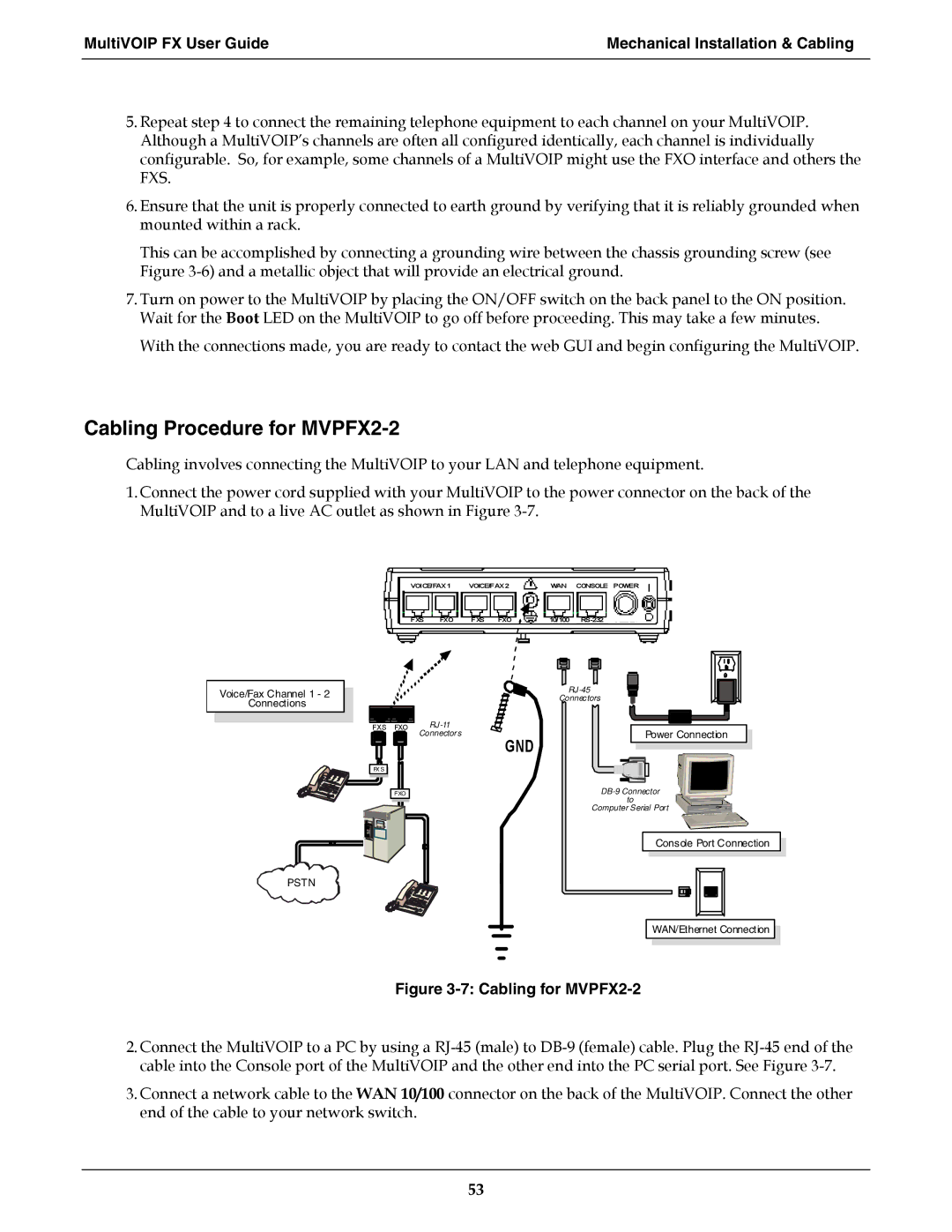
Cabling involves connecting the MultiVOIP to your LAN and telephone equipment.
1.Connect the power cord supplied with your MultiVOIP to the power connector on the back of the MultiVOIP and to a live AC outlet as shown in Figure
VOICE/FAX 1 | VOICE/FAX 2 |
| WAN | CONSOLE | POWER | ||||||||
|
|
|
|
|
|
|
|
|
|
| |||
FXS | FXO | FXS FXO | 10/100 |
|
|
| |||||||
|
|
|
|
|
|
|
|
|
|
|
|
|
|
|
|
|
|
|
|
|
|
|
|
|
|
|
|
|
|
|
|
|
|
|
|
|
|
|
|
|
|
Voice/Fax Channel 1 - 2
Connections
Connectors
FXS FXO | |
| Connectors |
FX S |
|
GND
Power Connection
PSTN
FXO |
to
Computer Serial Port
Console Port Connection
WAN/Ethernet Connection
Figure 3-7: Cabling for MVPFX2-2
2.Connect the MultiVOIP to a PC by using a
3.Connect a network cable to the WAN 10/100 connector on the back of the MultiVOIP. Connect the other end of the cable to your network switch.
53