maintenance
spark arrester cleaning
Clean the spark arrester every 6 months or 100 hours.
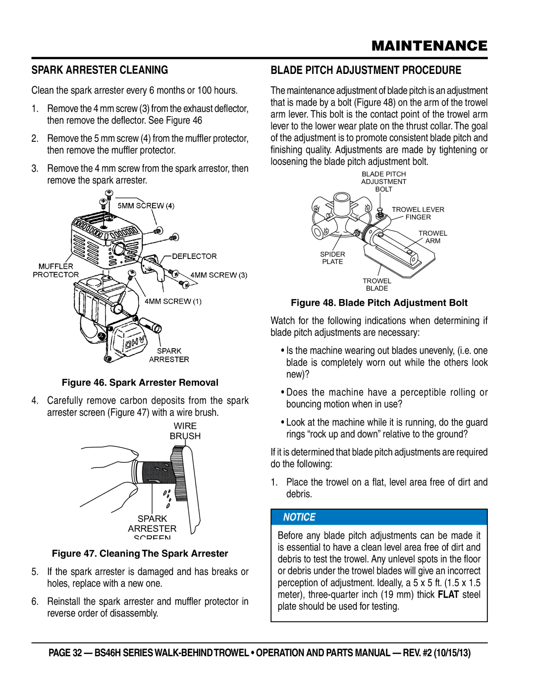
1.Remove the 4 mm screw (3) from the exhaust deflector, then remove the deflector. See Figure 46
2.Remove the 5 mm screw (4) from the muffler protector, then remove the muffler protector.
3.Remove the 4 mm screw from the spark arrestor, then remove the spark arrester.
Figure 46. Spark Arrester Removal
4.Carefully remove carbon deposits from the spark arrester screen (Figure 47) with a wire brush.
WIRE
BRUSH
SPARK
ARRESTER
SCREEN
Figure 47. Cleaning The Spark Arrester
5.If the spark arrester is damaged and has breaks or holes, replace with a new one.
6.Reinstall the spark arrester and muffler protector in reverse order of disassembly.
Blade Pitch Adjustment Procedure
The maintenance adjustment of blade pitch is an adjustment that is made by a bolt (Figure 48) on the arm of the trowel arm lever. This bolt is the contact point of the trowel arm lever to the lower wear plate on the thrust collar. The goal of the adjustment is to promote consistent blade pitch and finishing quality. Adjustments are made by tightening or loosening the blade pitch adjustment bolt.
BLADE PITCH
ADJUSTMENT
BOLT
TROWEL LEVER
FINGER
TROWEL
![]() ARM
ARM
SPIDER
PLATE
TROWEL
BLADE
Figure 48. Blade Pitch Adjustment Bolt
Watch for the following indications when determining if blade pitch adjustments are necessary:
•Is the machine wearing out blades unevenly, (i.e. one blade is completely worn out while the others look new)?
•Does the machine have a perceptible rolling or bouncing motion when in use?
•Look at the machine while it is running, do the guard rings “rock up and down” relative to the ground?
If it is determined that blade pitch adjustments are required do the following:
1.Place the trowel on a flat, level area free of dirt and debris.
![]() NOTICE
NOTICE
Before any blade pitch adjustments can be made it is essential to have a clean level area free of dirt and debris to test the trowel. Any unlevel spots in the floor or debris under the trowel blades will give an incorrect perception of adjustment. Ideally, a 5 x 5 ft. (1.5 x 1.5 meter),
page 32 — BS46H SERIES