Model BS46HLE
Fuel and chemical exposure Warnings
Silicosis/Respiratory Warnings
Silicosis Warning
Table of Contents
WALK-BEHIND Trowel
Training checklist
Completely
Daily pre-operation checklist
Daily pre-Operation checklist
Safety Information
SaFeTy meSSageS
GENEraL SafETy
Order Form PT-160
TrOwEL SafETy
ENgiNE SafETy
Before servicing equipment
FUeL SaFeTy
TraNSpOrTiNg SafETy
Emission control Label
ENvIRONmeNTaL SaFeTy/DeCOmmISSIONINg
EmISSIONS INFORmaTION
Label must remain with the engine for its entire life
Trowel SPECIFICATIONS/DIMENSIONS
Side View
Engine Specifications
11997+A12010 in m/s2 ΣA8
General information
Trowel Components
15 14 13 12
Engine Components
Initial Servicing
Handle Tube Installation
Assembly and installation
Assembly and Installation
Vibratory T-Handle Bar Placement
Shown in Figure
Safety Stop Switch Connection
Pitch Cable Installation
Ground point
Before Starting
Inspection
Engine Oil Check
Belt Guard Check
Gearbox Oil
Belt Check
Fuel Check
Lifting the Trowel Onto a Slab
Inspection/operation
Operation
Lifting Bale
Place the engine fuel valve lever in the on position
Operation
Starting the Engine
Place the choke lever in the Open position
Testing the Centrifugal Safety Stop Switch
Starter Grip
Pitching the Blades Standard Handle
To Begin Troweling
Concrete Finishing Techniques
Pitching the Blades Quick Pitch Handle
Maneuvering the Trowel
Maneuvering the Trowel
Place the safety stop switch in the OFF position
Stopping The Engine
Clip-On Float Blades Optional
Options
Combo Blades
Float Discs Optional
Trowel Arm Adjustment Tool Optional
Quick Pitch Handle Optional
Maintenance
Engine Air Cleaner
General Cleanliness
Engine check
Belt
Engine oil
Spark Plug
Never use a spark plug of incorrect heat range
Spark arrester cleaning
Blade Pitch Adjustment Procedure
Spider removal
Bushings or bent trowel arms
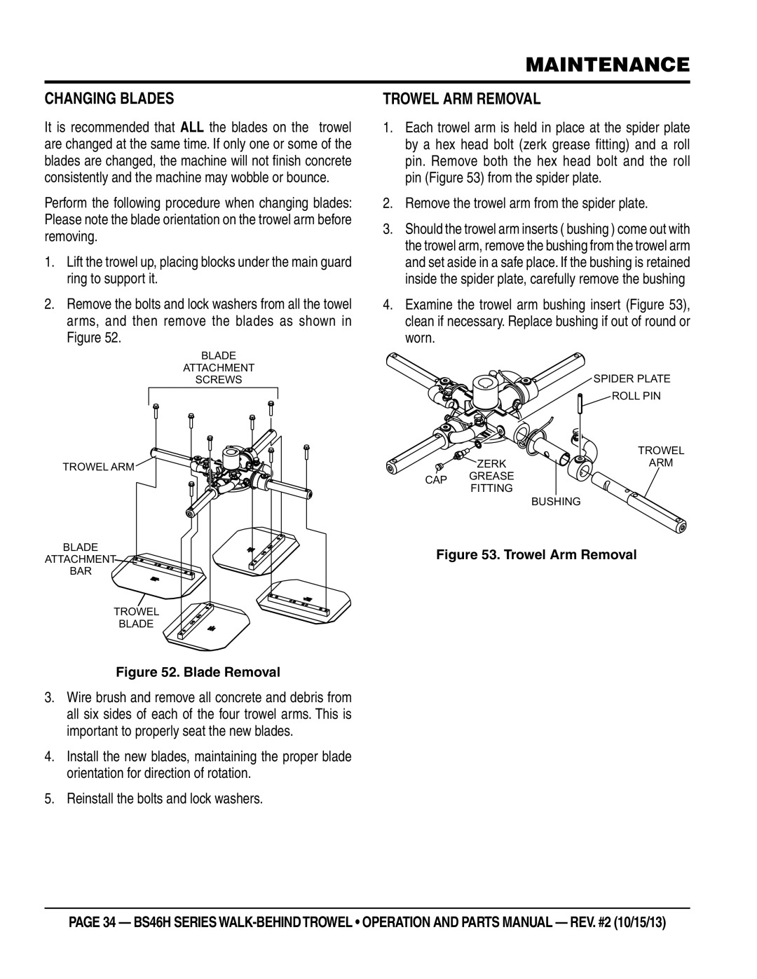
Trowel arm removal
Changing blades
Remove the trowel arm from the spider plate
Ensure the fixture arm is in the up position
Trowel arm Lever adjustment
Checking trowel arm straightness
Shaft and the test surface
ReAssembly
Installing Pans Onto Finisher Blades
LONG-TERM Storage
Troubleshooting
Troubleshooting engine
Air cleaner dirty? Clean or replace air cleaner
Or malfunctioning? Or replace switch if necessary
Troubleshooting Walk-Behind Trowel
Wiring Diagram
Page
Explanation of Code in Remarks Column
Suggested Spare Parts
To 3 Units
Nameplate and Decals
ISO DECAL, ASK for TRAINING, 2.00 DIA
ISO DECAL, Read MANUAL, 2.00 DIA
ISO DECAL, LIFTING/CRUSH, 2.4 X
DECAL, Serial PLATE, WBT-CHINA
Standard Handle Assy
SPACER, Slide Block Guide
Wire ASSY., Kill Switch
Switch ASSY., Kill
WASHER, FENDER, 1.5OD X 3/8ID
Quick-pitch Handle ASSY. option
QP Adjustment Block
NUT , QP Trim Cntl Adjustment
Adjustment PIN
Spring Center Balance
Guard Assy
CLIP, Fast Lead
Access PANEL, B Finisher
Guard Ring
SCREW, Fast Lead
Gearbox Assy
Requires 26 OZ .8 Liters Gearbox Lubricant for Operation
BEARING, CUP, Timken #M11910
SEAL, OIL
FLANGE, Input Shaft
GEAR, Worm B Input Shaft
Engine and clutch Assy
Lifting Bale Assembly B FIN
CONNECTOR, Splice TAP
WIRE, Safety Switch
WEIGHT, Automatic Clutch
Spider Assy
14 1
BUSHING, Trowel ARM
Blade Assembly
Lock Washer 3/8 MED
Spider Plate
Stabilizer Ring Assy
1237
0300B
RING, STABILIZER, 16-1/2 ARM
Blade Assy
0201
21906
See Notice below
Guard Ring LUG Ring
Engine service parts
28462ZE3W01
17620Z4H020
28462ZE2W11
17210ZE2822
Page
Page
HERE’S HOW to GET Help