assembly and installation
Assembly and Installation
Before the trowel can be put into operation there are some components that must be installed before the trowel can be used.This section provides general instructions on how to install those components. Instruction sheet P/N 20485 provides further details for the handle assembly.
Handle Tube Installation
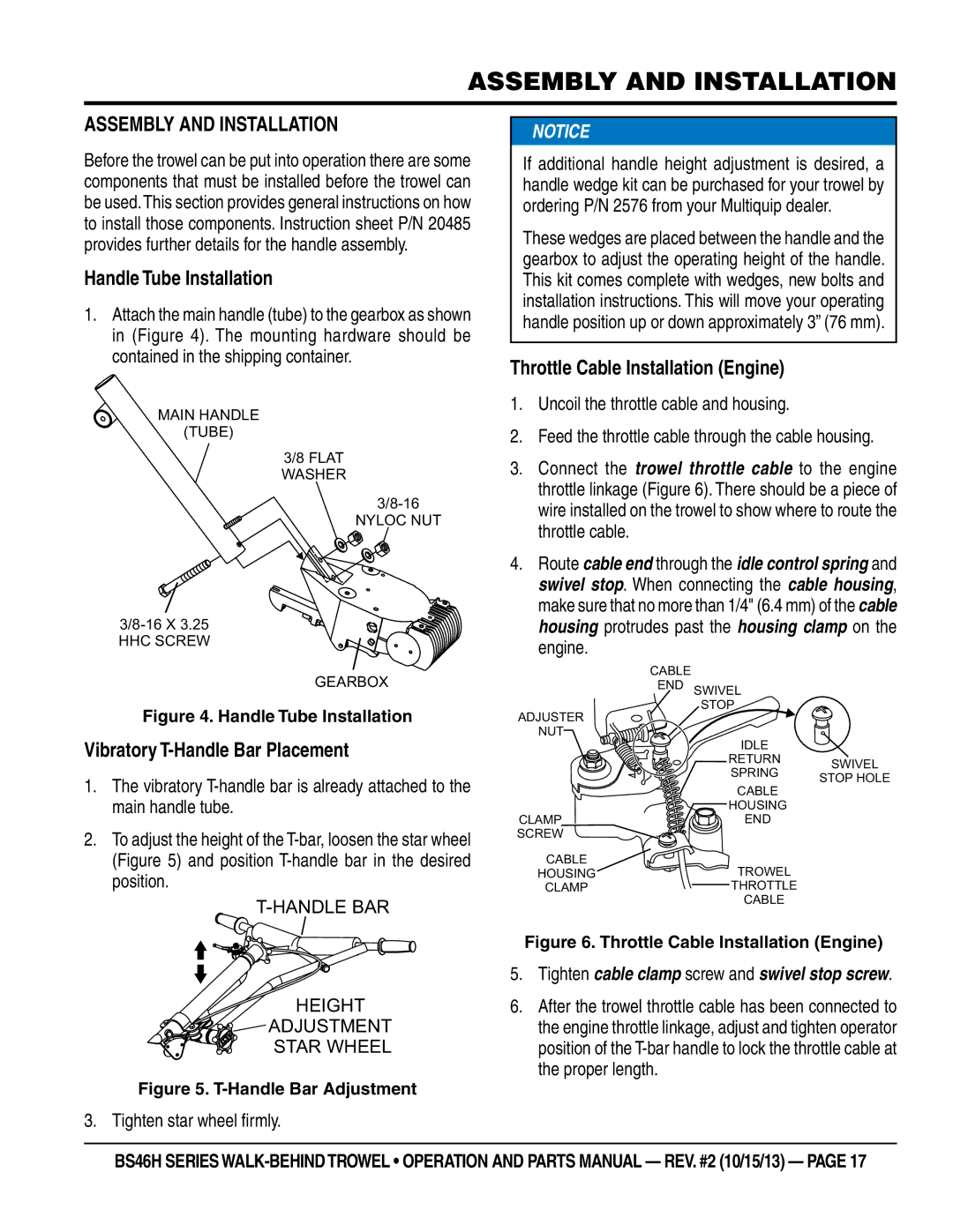
1.Attach the main handle (tube) to the gearbox as shown in (Figure 4). The mounting hardware should be contained in the shipping container.
MAIN HANDLE
(TUBE)
3/8 FLAT WASHER
NYLOC NUT
GEARBOX
Figure 4. Handle Tube Installation
Vibratory T-Handle Bar Placement
1.The vibratory
2.To adjust the height of the
T-HANDLE BAR
HEIGHT
 ADJUSTMENT
STAR WHEEL
Figure 5. T-Handle Bar Adjustment
![]() NOTICE
NOTICE
If additional handle height adjustment is desired, a handle wedge kit can be purchased for your trowel by ordering P/N 2576 from your Multiquip dealer.
These wedges are placed between the handle and the gearbox to adjust the operating height of the handle. This kit comes complete with wedges, new bolts and installation instructions. This will move your operating handle position up or down approximately 3” (76 mm).
Throttle Cable Installation (Engine)
1.Uncoil the throttle cable and housing.
2.Feed the throttle cable through the cable housing.
3.Connect the trowel throttle cable to the engine throttle linkage (Figure 6). There should be a piece of wire installed on the trowel to show where to route the throttle cable.
4.Route cable end through the idle control spring and swivel stop. When connecting the cable housing, make sure that no more than 1/4" (6.4 mm) of the cable housing protrudes past the housing clamp on the engine.
CABLE
END SWIVEL
STOP
ADJUSTER
NUT
IDLE |
| |
RETURN | SWIVEL | |
SPRING | ||
STOP HOLE | ||
|
| CABLE |
| HOUSING |
CLAMP | END |
SCREW |
|
CABLE |
|
HOUSING | TROWEL |
CLAMP | THROTTLE |
| CABLE |
Figure 6. Throttle Cable Installation (Engine)
5.Tighten cable clamp screw and swivel stop screw.
6.After the trowel throttle cable has been connected to the engine throttle linkage, adjust and tighten operator position of the
3. Tighten star wheel firmly.
BS46H SERIES