maintenance
checking trowel arm straightness
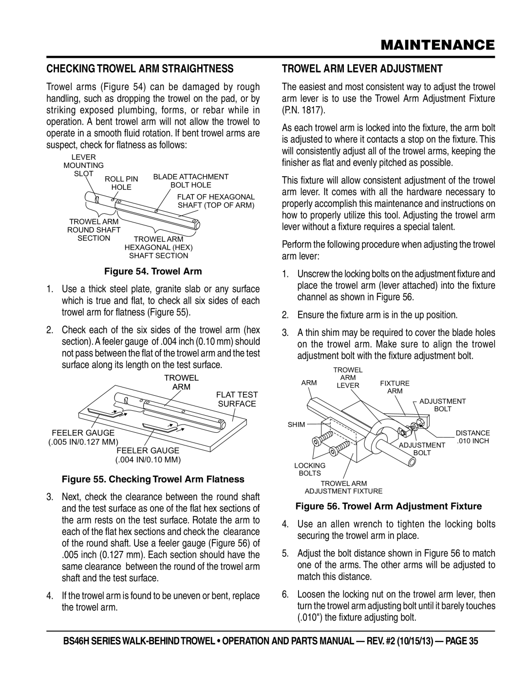
Trowel arms (Figure 54) can be damaged by rough handling, such as dropping the trowel on the pad, or by striking exposed plumbing, forms, or rebar while in operation. A bent trowel arm will not allow the trowel to operate in a smooth fluid rotation. If bent trowel arms are suspect, check for flatness as follows:
LEVER |
|
|
MOUNTING |
|
|
SLOT | ROLL PIN | BLADE ATTACHMENT |
| ||
| BOLT HOLE | |
| HOLE | |
|
| |
|
| FLAT OF HEXAGONAL |
|
| SHAFT (TOP OF ARM) |
TROWEL ARM
ROUND SHAFT
SECTION TROWEL ARM
HEXAGONAL (HEX)
SHAFT SECTION
Figure 54. Trowel Arm
1.Use a thick steel plate, granite slab or any surface which is true and flat, to check all six sides of each trowel arm for flatness (Figure 55).
2.Check each of the six sides of the trowel arm (hex section). A feeler gauge of .004 inch (0.10 mm) should not pass between the flat of the trowel arm and the test surface along its length on the test surface.
TROWEL
ARM
FLAT TEST
SURFACE
FEELER GAUGE
trowel arm Lever adjustment
The easiest and most consistent way to adjust the trowel arm lever is to use the Trowel Arm Adjustment Fixture (P.N. 1817).
As each trowel arm is locked into the fixture, the arm bolt is adjusted to where it contacts a stop on the fixture. This will consistently adjust all of the trowel arms, keeping the finisher as flat and evenly pitched as possible.
This fixture will allow consistent adjustment of the trowel arm lever. It comes with all the hardware necessary to properly accomplish this maintenance and instructions on how to properly utilize this tool. Adjusting the trowel arm lever without a fixture requires a special talent.
Perform the following procedure when adjusting the trowel arm lever:
1.Unscrew the locking bolts on the adjustment fixture and place the trowel arm (lever attached) into the fixture channel as shown in Figure 56.
2.Ensure the fixture arm is in the up position.
3.A thin shim may be required to cover the blade holes on the trowel arm. Make sure to align the trowel adjustment bolt with the fixture adjustment bolt.
TROWEL
ARM
ARM LEVER FIXTURE
ARM
ADJUSTMENT
BOLT
SHIM
DISTANCE
(.005 IN/0.127 MM)
FEELER GAUGE
(.004 IN/0.10 MM)
Figure 55. Checking Trowel Arm Flatness
3. Next, check the clearance between the round shaft |
ADJUSTMENT
BOLT
LOCKING
BOLTS
TROWEL ARM
ADJUSTMENT FIXTURE
.010 INCH
and the test surface as one of the flat hex sections of |
the arm rests on the test surface. Rotate the arm to |
each of the flat hex sections and check the clearance |
of the round shaft. Use a feeler gauge (Figure 56) of |
.005 inch (0.127 mm). Each section should have the |
same clearance between the round of the trowel arm |
shaft and the test surface. |
4. If the trowel arm is found to be uneven or bent, replace |
the trowel arm. |
Figure 56. Trowel Arm Adjustment Fixture
4.Use an allen wrench to tighten the locking bolts securing the trowel arm in place.
5.Adjust the bolt distance shown in Figure 56 to match one of the arms. The other arms will be adjusted to match this distance.
6.Loosen the locking nut on the trowel arm lever, then turn the trowel arm adjusting bolt until it barely touches (.010") the fixture adjusting bolt.
BS46H SERIES