maintenance
7.Once the correct adjustment is made, tighten the lock nut on the trowel arm to lock in place.
8.Loosen locking nuts on the adjustment fixture, and remove trowel arm.
9.Repeat steps for the remaining trowel arms.
ReAssembly
1.Clean and examine the upper/lower wear plates and thrust collar. Examine the entire spider assembly. Wire brush any concrete or rust buildup. If any of the spider components are found to be damaged or out of round, replace them.
2.Make sure that the bronze trowel arm bushing is not damage or out of round. Clean the bushing if necessary. If the bronze bushing is damaged or worn, replace it.
3.Reinstall bronze bushing onto trowel arm.
4.Repeat steps 2
5.Make sure that the spring tensioner is in the correct position to exert tension on the trowel arm.
6.Insert all trowel arms with levers into spider plate (with bronze bushing already installed) using care to align grease hole on bronze bushing with grease hole fitting on spider plate.
7.Lock trowel arms in place by tightening the hex head bolt with zerk grease fitting and jam nut.
8.Reinstall the blades onto the trowel arms.
9.Install stabilizer ring onto spider assembly.
10.Reinstall lower wear plate, thrust collar and upper wear ring in the reverse order that they were disassembled onto the spider shaft. Make sure that there is little or no lateral movement between the thrust collar and the spider shaft.
11.Carefully lift the upper trowel assembly, line up the keyway on gear box main shaft and insert into spider assembly.
12.Reinstall square head cone point into spider plate and tighten in place. Tighten jam nut. Use care in making sure point of set screw engages groove in gear box main shaft.
13.Lubricate all grease points (zerk fittings) with premium "Lithium 12" based grease, conforming to NLG1 Grade #2 consistency.
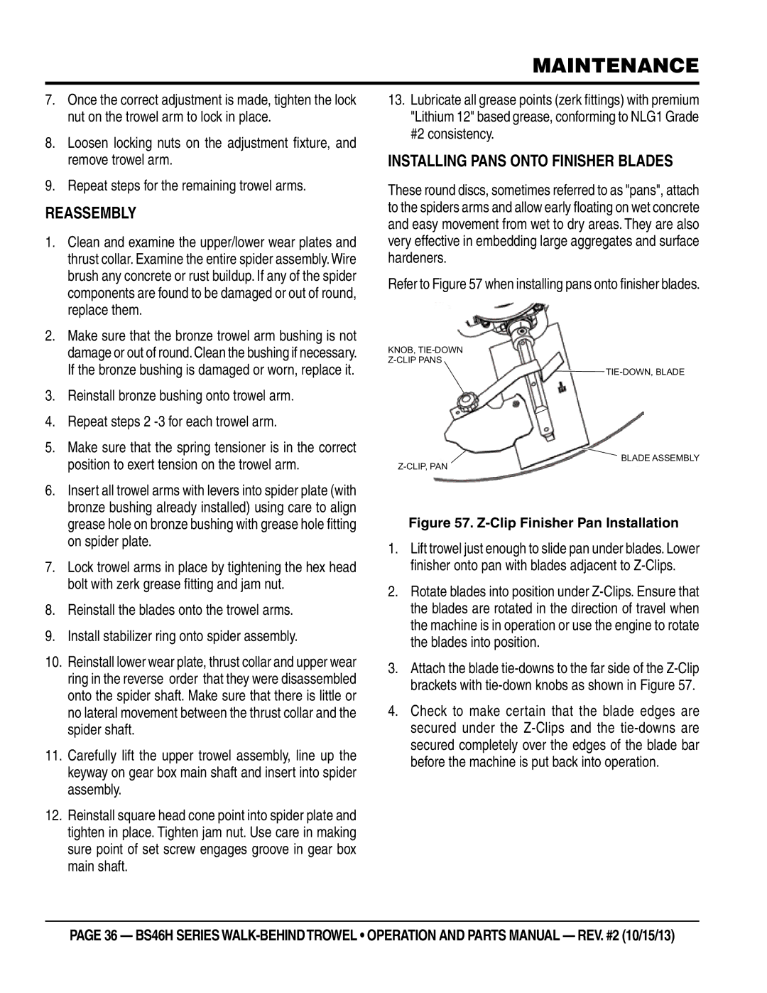
Installing Pans Onto Finisher Blades
These round discs, sometimes referred to as "pans", attach to the spiders arms and allow early floating on wet concrete and easy movement from wet to dry areas. They are also very effective in embedding large aggregates and surface hardeners.
Refer to Figure 57 when installing pans onto finisher blades.
KNOB,
BLADE ASSEMBLY
Figure 57. Z-Clip Finisher Pan Installation
1.Lift trowel just enough to slide pan under blades. Lower finisher onto pan with blades adjacent to
2.Rotate blades into position under
3.Attach the blade
4.Check to make certain that the blade edges are secured under the
page 36 — BS46H SERIES