trowel COMPONENTS
4 5
3
2
10 9
1
15 14 13 12 11
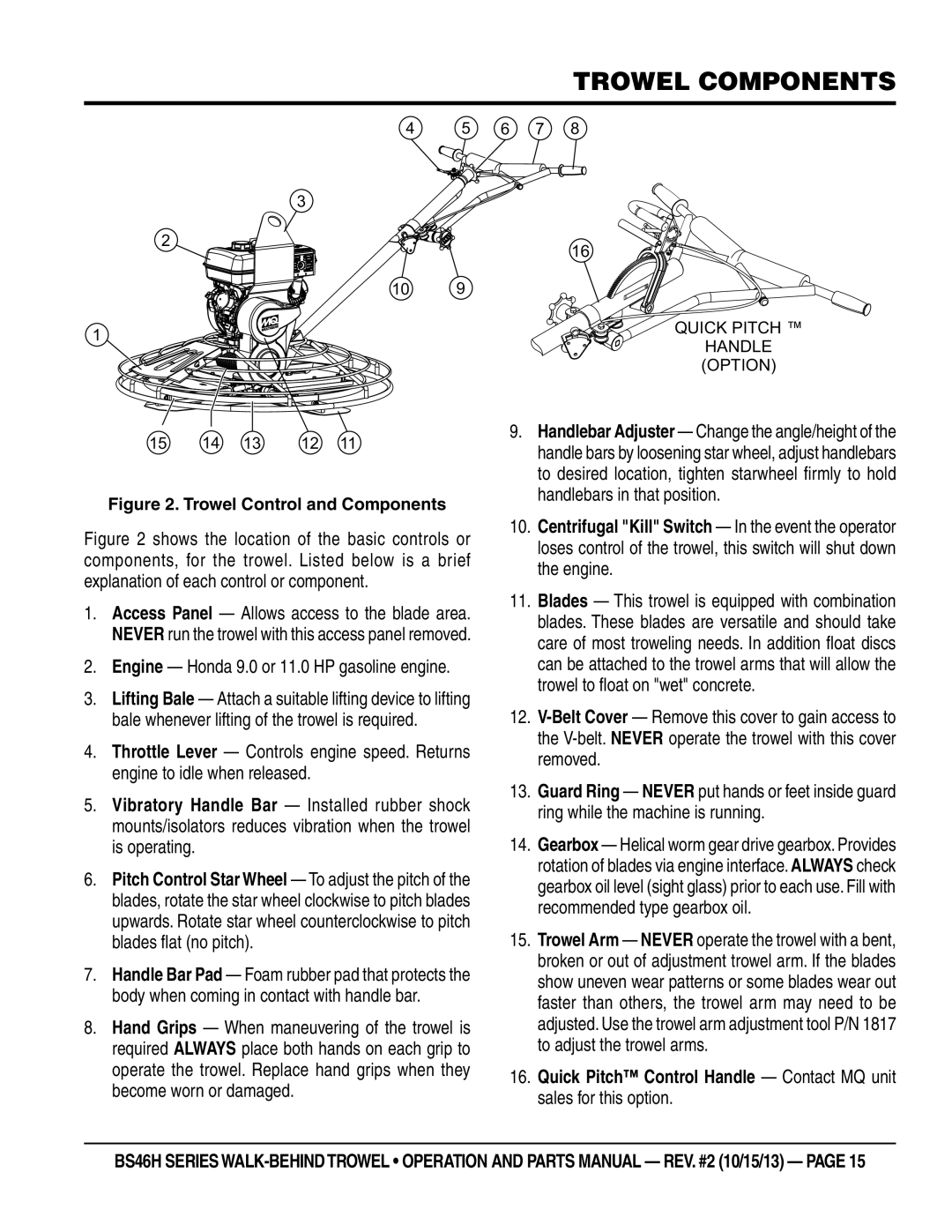
Figure 2. Trowel Control and Components
Figure 2 shows the location of the basic controls or components, for the trowel. Listed below is a brief explanation of each control or component.
1.Access Panel — Allows access to the blade area. NEVER run the trowel with this access panel removed.
2.Engine — Honda 9.0 or 11.0 HP gasoline engine.
3.Lifting Bale — Attach a suitable lifting device to lifting bale whenever lifting of the trowel is required.
4.Throttle Lever — Controls engine speed. Returns engine to idle when released.
5.Vibratory Handle Bar — Installed rubber shock mounts/isolators reduces vibration when the trowel is operating.
6.Pitch Control Star Wheel — To adjust the pitch of the blades, rotate the star wheel clockwise to pitch blades upwards. Rotate star wheel counterclockwise to pitch blades flat (no pitch).
7.Handle Bar Pad — Foam rubber pad that protects the body when coming in contact with handle bar.
8.Hand Grips — When maneuvering of the trowel is required ALWAYS place both hands on each grip to operate the trowel. Replace hand grips when they become worn or damaged.
6 7 8
16
QUICK PITCH ™
HANDLE (OPTION)
9.Handlebar Adjuster — Change the angle/height of the handle bars by loosening star wheel, adjust handlebars to desired location, tighten starwheel firmly to hold handlebars in that position.
10.Centrifugal "Kill" Switch — In the event the operator loses control of the trowel, this switch will shut down the engine.
11.Blades — This trowel is equipped with combination blades. These blades are versatile and should take care of most troweling needs. In addition float discs can be attached to the trowel arms that will allow the trowel to float on "wet" concrete.
12.
13.Guard Ring — NEVER put hands or feet inside guard ring while the machine is running.
14.Gearbox — Helical worm gear drive gearbox. Provides rotation of blades via engine interface. ALWAYS check gearbox oil level (sight glass) prior to each use. Fill with recommended type gearbox oil.
15.Trowel Arm — NEVER operate the trowel with a bent, broken or out of adjustment trowel arm. If the blades show uneven wear patterns or some blades wear out faster than others, the trowel arm may need to be adjusted. Use the trowel arm adjustment tool P/N 1817 to adjust the trowel arms.
16.Quick Pitch™ Control Handle — Contact MQ unit sales for this option.
BS46H SERIES