NETGEAR ProSafe 802.11g Wireless Access Point WG102 Reference Manual
LED | Description |
|
|
|
|
LAN | Ethernet link indicator | |
|
|
|
| Off | No connection detected on the Ethernet link |
|
|
|
| Amber On | 10 Mbps Ethernet link detected |
|
|
|
| Amber Flashing | Data is being transmitted or received on the 10 Mbps Ethernet link |
|
|
|
| Green On | 100 Mbps Fast Ethernet link detected. |
|
|
|
| Green Flashing | Data is being transmitted or received on the 100 Mbps Ethernet link |
|
|
|
WLAN | Wireless LAN Link Activity Indicator | |
|
|
|
| Off | No wireless link activity. |
|
|
|
| Green Blink | Wireless link activity. |
|
|
|
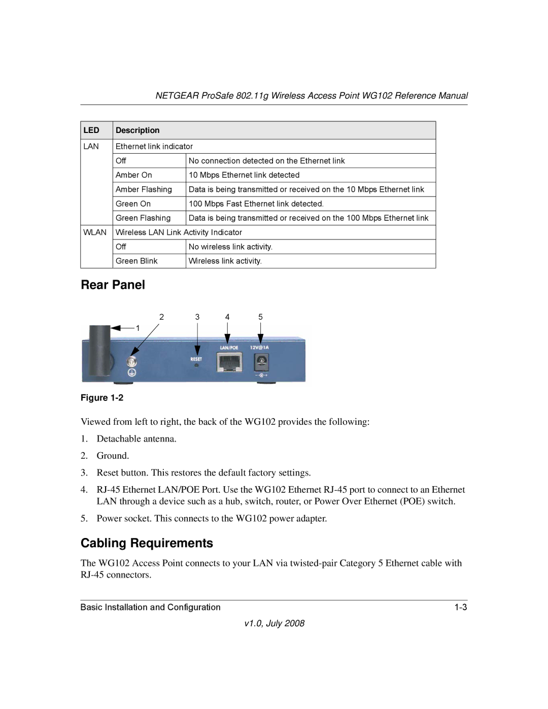
Rear Panel
2 3 4 5
1
Figure
Viewed from left to right, the back of the WG102 provides the following:
1.Detachable antenna.
2.Ground.
3.Reset button. This restores the default factory settings.
4.
5.Power socket. This connects to the WG102 power adapter.
Cabling Requirements
The WG102 Access Point connects to your LAN via
Basic Installation and Configuration |