Connecting peripherals to the server 29
Figure 7
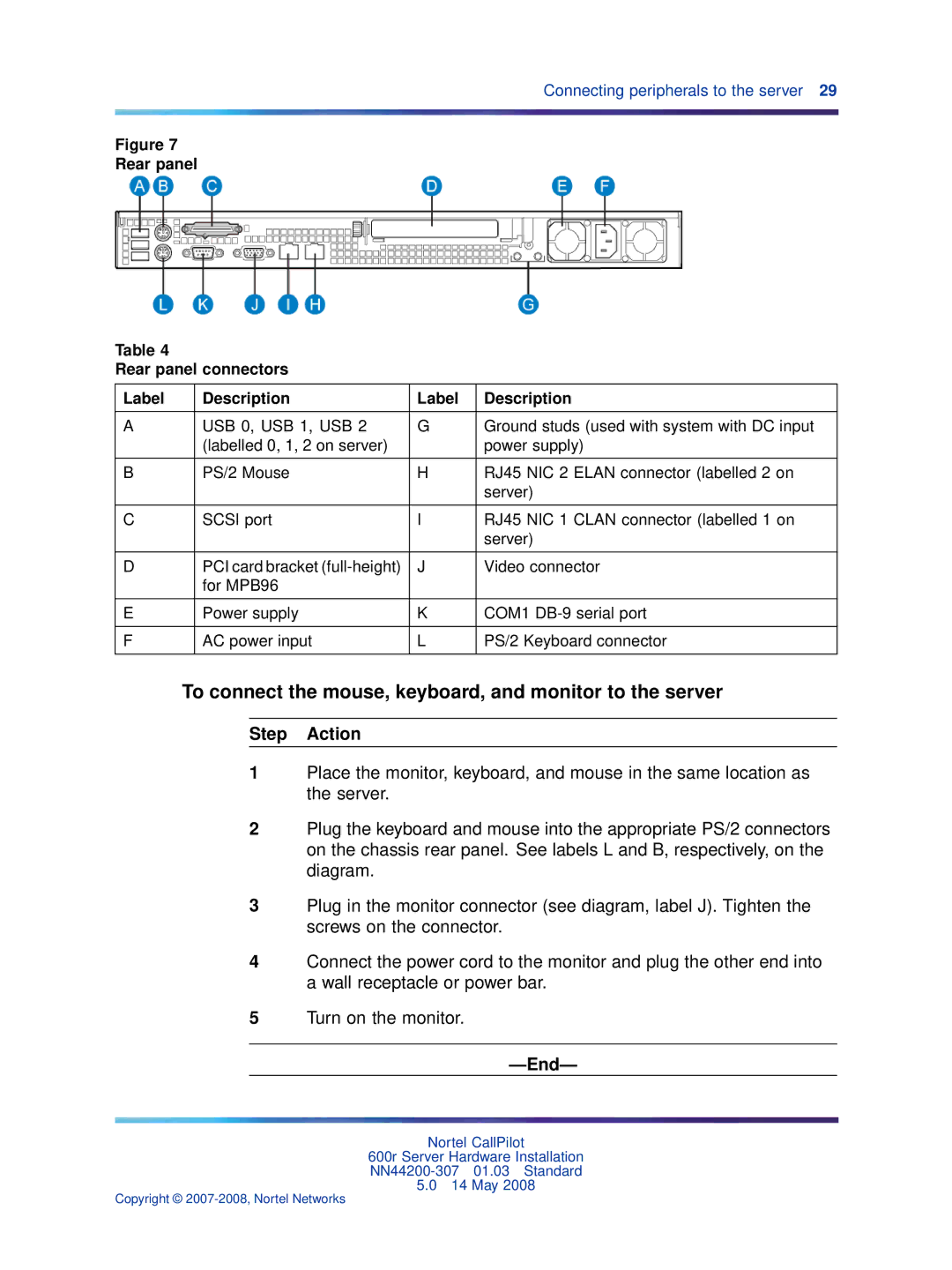
Rear panel
Table 4
Rear panel connectors
Label | Description | Label | Description |
|
|
|
|
A | USB 0, USB 1, USB 2 | G | Ground studs (used with system with DC input |
| (labelled 0, 1, 2 on server) |
| power supply) |
|
|
|
|
B | PS/2 Mouse | H | RJ45 NIC 2 ELAN connector (labelled 2 on |
|
|
| server) |
|
|
|
|
C | SCSI port | I | RJ45 NIC 1 CLAN connector (labelled 1 on |
|
|
| server) |
|
|
|
|
D | PCI card bracket | J | Video connector |
| for MPB96 |
|
|
|
|
|
|
E | Power supply | K | COM1 |
|
|
|
|
F | AC power input | L | PS/2 Keyboard connector |
|
|
|
|
To connect the mouse, keyboard, and monitor to the server
Step Action
1Place the monitor, keyboard, and mouse in the same location as the server.
2Plug the keyboard and mouse into the appropriate PS/2 connectors on the chassis rear panel. See labels L and B, respectively, on the diagram.
3Plug in the monitor connector (see diagram, label J). Tighten the screws on the connector.
4Connect the power cord to the monitor and plug the other end into a wall receptacle or power bar.
5Turn on the monitor.
Nortel CallPilot
600r Server Hardware Installation
5.014 May 2008
Copyright ©