3.2 Changing the Meter Parameters
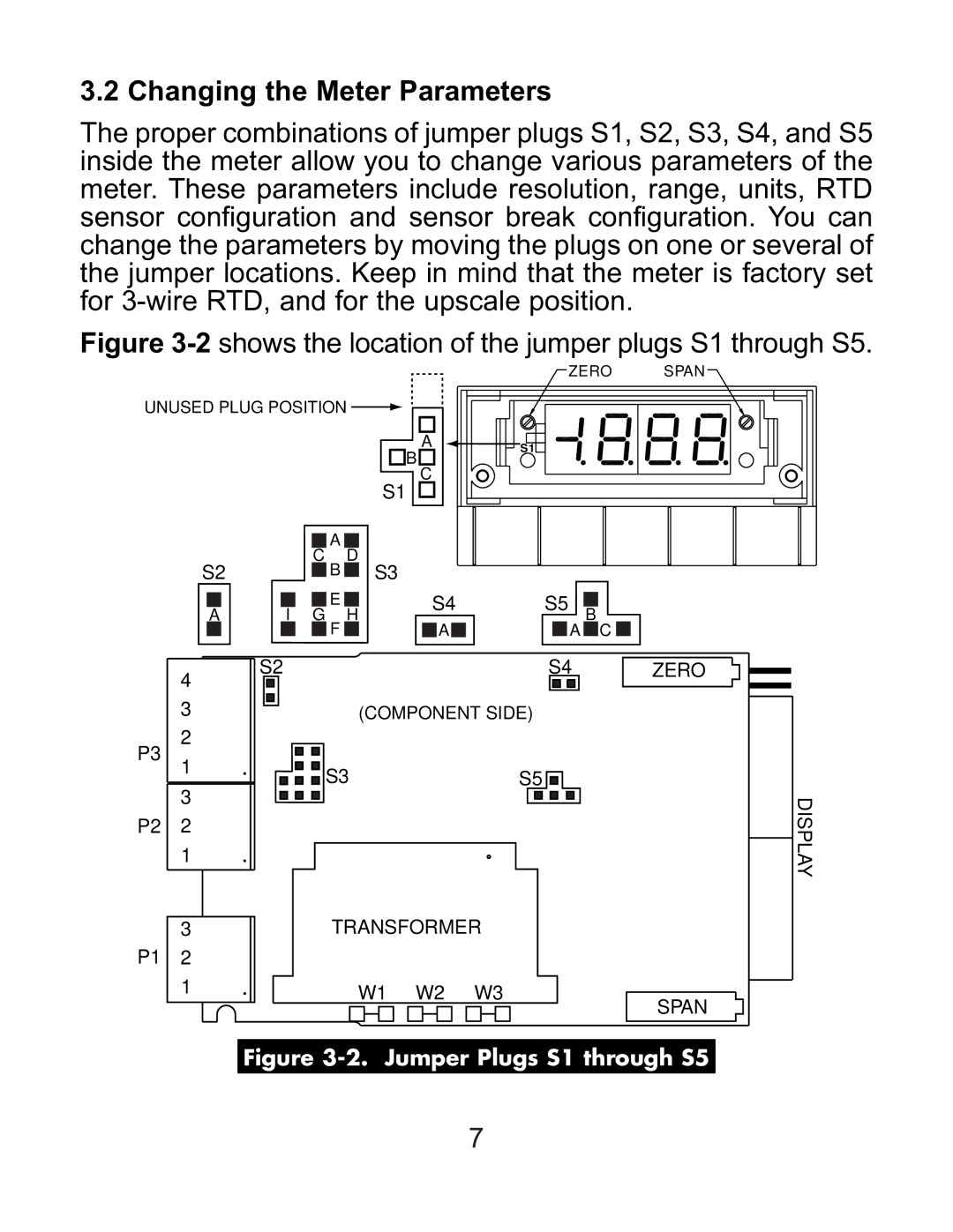
The proper combinations of jumper plugs S1, S2, S3, S4, and S5 inside the meter allow you to change various parameters of the meter. These parameters include resolution, range, units, RTD sensor configuration and sensor break configuration. You can change the parameters by moving the plugs on one or several of the jumper locations. Keep in mind that the meter is factory set for
Figure 3-2 shows the location of the jumper plugs S1 through S5.
ZERO SPAN
UNUSED PLUG POSITION ![]()
A | S1 | |
B | ||
| ||
C |
|
S1
S2
A
4
3
2
P3
1
3
P2 2
1
3
P1 2
1
|
|
|
|
|
|
|
|
| A |
|
|
|
|
|
|
|
|
|
|
|
|
|
|
|
|
|
|
|
|
|
|
|
|
|
| C | B | D | S3 |
|
|
|
|
|
|
|
|
| |||||||||
|
|
|
|
|
|
|
|
|
|
|
|
|
|
|
|
|
|
| ||||||||||
|
|
|
|
|
|
|
|
|
|
|
|
|
|
|
|
|
|
| ||||||||||
|
|
|
|
|
|
|
|
| E |
|
|
| S4 | S5 |
|
|
|
| ||||||||||
|
|
|
|
|
|
|
|
|
|
|
|
|
|
|
| |||||||||||||
|
|
| I |
| G | F | H |
|
| B |
|
|
| |||||||||||||||
|
|
|
|
|
|
|
| A |
|
|
|
|
|
|
|
| A | C |
|
| ||||||||
|
|
|
|
|
|
|
|
|
|
|
|
|
|
|
|
|
|
|
|
|
| |||||||
S2 |
|
|
|
|
|
|
|
|
|
|
| S4 |
|
|
| ZERO | ||||||||||||
|
|
|
|
|
|
|
|
|
|
|
|
|
| |||||||||||||||
|
|
|
|
|
|
|
|
|
|
| (COMPONENT SIDE) |
|
|
|
|
|
|
|
|
| ||||||||
|
|
|
|
|
|
|
|
|
|
|
|
|
|
|
|
|
|
|
| |||||||||
|
|
|
|
|
|
|
|
|
|
|
|
|
|
|
|
|
|
|
| |||||||||
|
|
|
|
|
|
|
|
|
|
|
|
|
|
|
|
|
|
|
| |||||||||
|
|
|
|
|
|
|
|
| S3 |
|
|
|
|
|
| S5 |
|
|
|
|
|
|
|
|
| |||
|
|
|
|
|
|
|
|
|
|
|
|
|
|
|
|
|
|
|
|
|
|
|
| |||||
|
|
|
|
|
|
|
|
|
|
|
|
|
|
|
|
|
|
|
|
|
|
|
| |||||
|
|
|
|
|
|
|
|
|
|
|
|
|
|
|
|
|
|
|
|
|
|
|
| |||||
|
|
|
|
|
|
|
|
|
|
|
|
|
|
|
|
|
| |||||||||||
|
|
|
|
|
|
|
|
|
|
|
|
|
|
|
|
|
| |||||||||||
|
|
|
|
|
|
|
|
|
|
|
|
|
|
|
|
|
| |||||||||||
|
|
|
|
|
|
|
|
|
|
|
|
|
|
|
|
|
|
|
|
|
|
|
|
|
|
|
|
|
|
|
|
|
|
|
|
|
|
|
|
|
|
|
|
|
|
|
|
|
|
|
|
|
|
|
|
|
|
TRANSFORMER
W1 W2 W3
SPAN
DISPLAY
Figure 3-2. Jumper Plugs S1 through S5
7