DC WIRING
The meter can be configured at the factory to operate on a 9Ð26 VDC
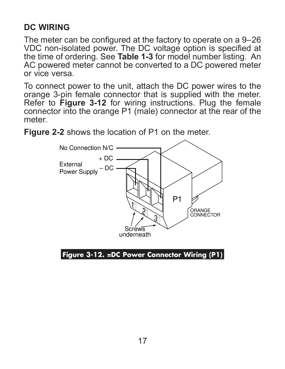
To connect power to the unit, attach the DC power wires to the orange
Figure 2-2 shows the location of P1 on the meter.
No Connection N/C
+ DC
External
Power Supply – DC
P1 1 ![]() 2
2 ![]()
![]() 3
3
Screws
underneath
ORANGE CONNECTOR
Figure 3-12. =DC Power Connector Wiring (P1)
17