OMEGA Model CYD201/CYD208 User’s Manual
2.4.2Connecting Leads To The Sensor
Excessive heat flow through connecting leads to any temperature sensor may differ the temperature between the active sensing element and the sample to which the sensor mounts. This reflects as a real temperature offset between what is measured and the true sample temperature. Eliminate such temperature errors with proper selection and installation of connecting leads.
To minimize heat flow through the leads, select leads of small diameter and low thermal conductivity.
Thermally anchor lead wires at several temperatures between room temperature and cryogenic temperatures to guarantee no heat conduction through the leads to the sensor.
2.4.3Sensor Mounting
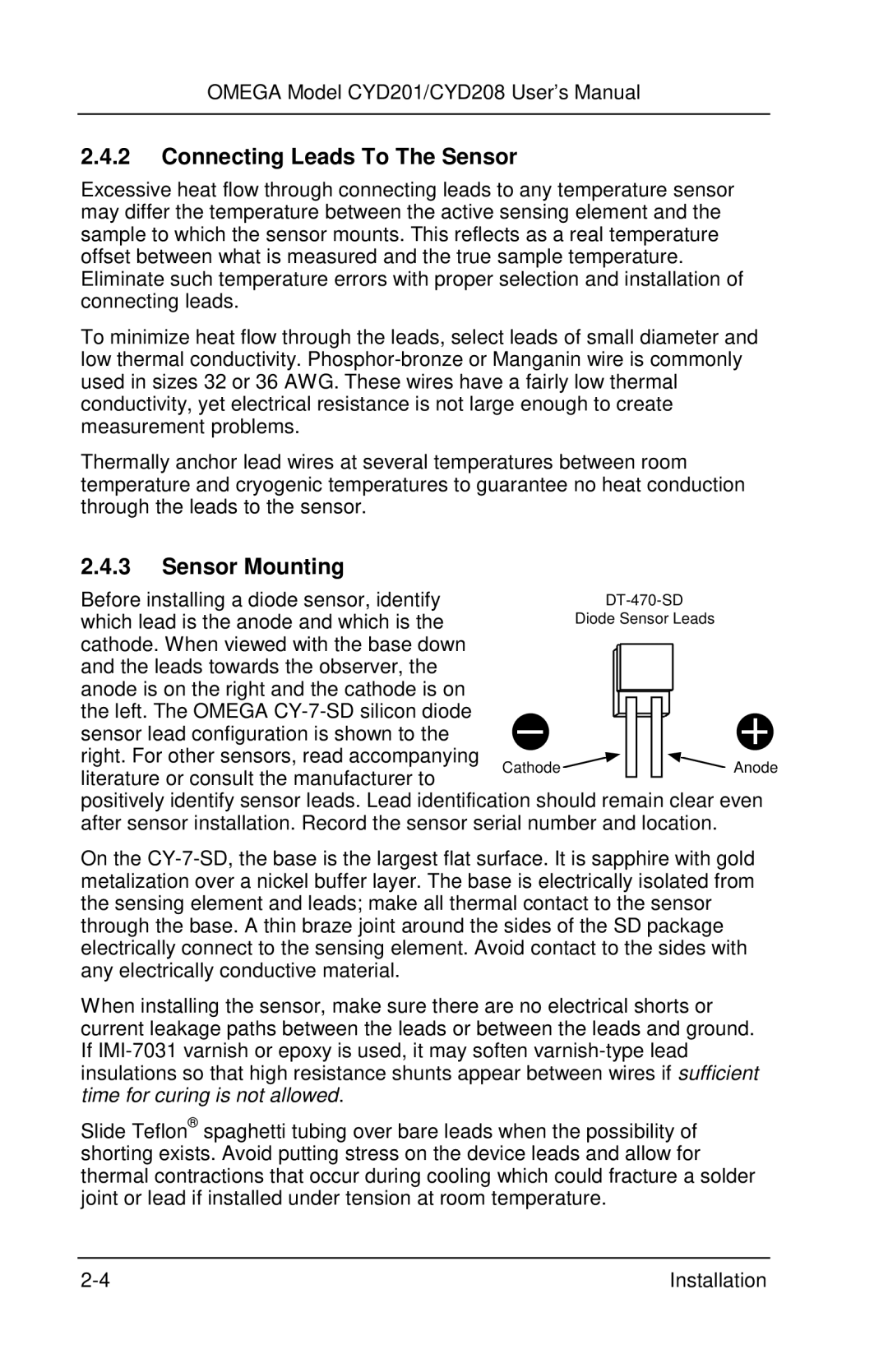
Before installing a diode sensor, identify |
| |||||||
which lead is the anode and which is the |
| Diode Sensor Leads | ||||||
cathode. When viewed with the base down |
|
|
|
|
|
|
|
|
and the leads towards the observer, the |
|
|
|
|
|
|
|
|
anode is on the right and the cathode is on |
|
|
|
|
|
|
|
|
the left. The OMEGA |
|
|
|
|
|
|
|
|
|
|
|
|
|
|
|
| |
sensor lead configuration is shown to the |
|
|
|
|
|
|
|
|
right. For other sensors, read accompanying | Cathode |
|
|
|
|
|
| Anode |
literature or consult the manufacturer to |
|
|
|
|
|
| ||
|
|
|
|
|
|
|
| |
positively identify sensor leads. Lead identification should remain clear even after sensor installation. Record the sensor serial number and location.
On the
When installing the sensor, make sure there are no electrical shorts or current leakage paths between the leads or between the leads and ground. If
Slide Teflon® spaghetti tubing over bare leads when the possibility of shorting exists. Avoid putting stress on the device leads and allow for thermal contractions that occur during cooling which could fracture a solder joint or lead if installed under tension at room temperature.
Installation |