OMEGA Model CYD201/CYD208 User’s Manual
CHAPTER 5
SERVICE
5.0GENERAL
This chapter covers Model CYD201/CYD208 maintenance: Model CYD201 Rear Panel Connections (Paragraph 5.1), Model CYD208 Rear Panel Connections (Paragraph 5.2), Error Code Troubleshooting (Paragraph 5.3), General Maintenance (Paragraph 5.4), Fuse Replacement (Paragraph 5.5), Line Voltage Selection (Paragraph 5.6), Calibration (Paragraph 5.7), and Serial Interface Cable and Adapters (Paragraph 5.8).
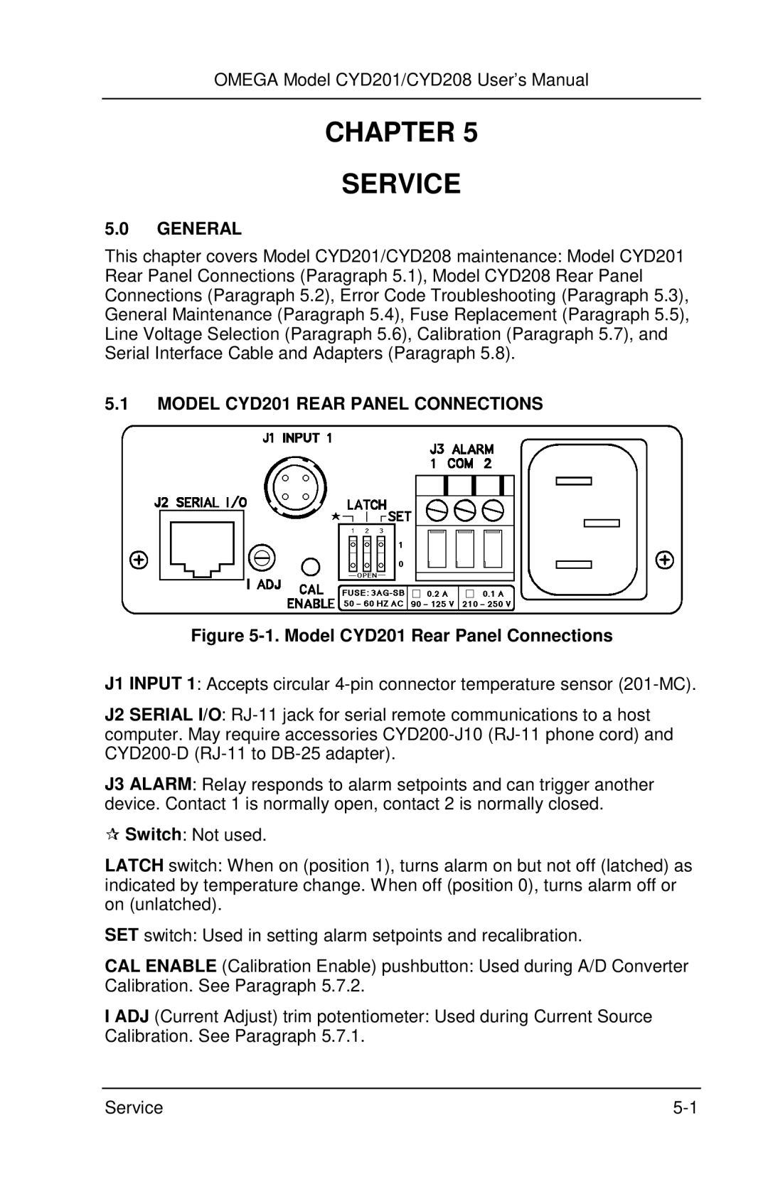
5.1MODEL CYD201 REAR PANEL CONNECTIONS
Figure 5-1. Model CYD201 Rear Panel Connections
J1 INPUT 1: Accepts circular
J2 SERIAL I/O:
J3 ALARM: Relay responds to alarm setpoints and can trigger another device. Contact 1 is normally open, contact 2 is normally closed.
Switch: Not used.
LATCH switch: When on (position 1), turns alarm on but not off (latched) as indicated by temperature change. When off (position 0), turns alarm off or on (unlatched).
SET switch: Used in setting alarm setpoints and recalibration.
CAL ENABLE (Calibration Enable) pushbutton: Used during A/D Converter Calibration. See Paragraph 5.7.2.
I ADJ (Current Adjust) trim potentiometer: Used during Current Source Calibration. See Paragraph 5.7.1.
Service |