OMEGA Model CYD201/CYD208 User’s Manual
5.5FUSE REPLACEMENT
WARNING: To prevent shock hazard, turn off instrument and disconnect it from AC line power and all test equipment before replacing fuse.
1.Turn POWER switch Off and disconnect power cord from unit. Disconnect all test equipment from unit.
2.Remove all screws from rear panel. Gently pull away rear panel and remove enclosure cover by sliding it to the back.
3.Remove fuse with a fuse puller. The fuse is located behind the transformer as shown in Figure 5.3.
4.Replace with a 0.2 A fuse for 110 V (115 VAC) operation or a 0.1 A fuse for 220 V (230 VAC) operation. Use slow blow fuses.
CAUTION: Replace fuse with the same type and rating as specified by the line voltage selected.
5. Replace enclosure cover, rear panel, and all screws.
5.6Line Voltage Configuration
The
WARNING: To prevent shock hazard, turn off instrument and disconnect it from AC line power and all test equipment before changing line voltage configuration.
1.Turn power switch OFF and disconnect the power cord from the unit. Disconnect all test equipment from unit.
2.Remove all screws from rear panel. Gently pull away rear panel and remove enclosure cover by sliding it to the back.
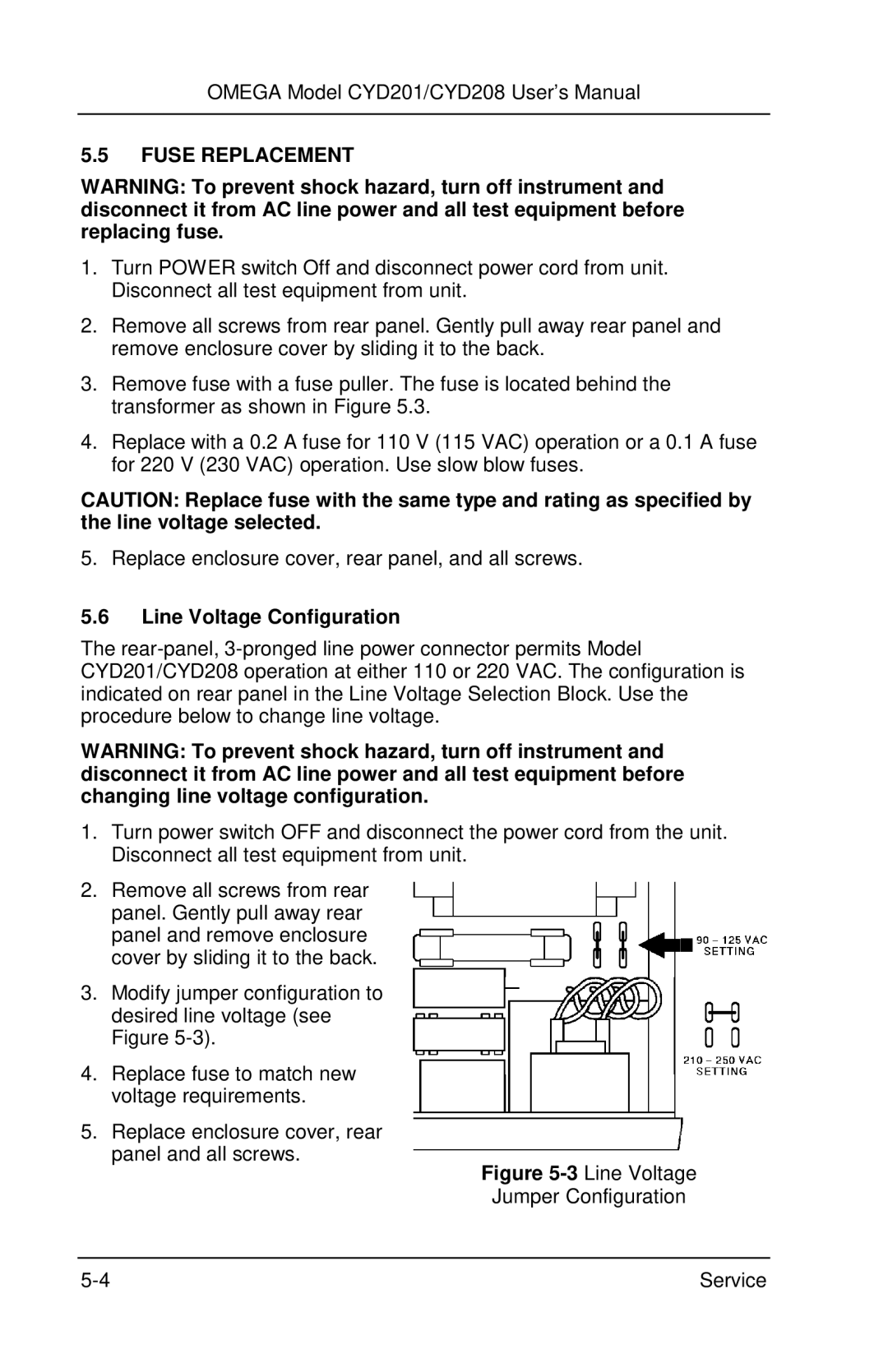
3.Modify jumper configuration to desired line voltage (see Figure
4.Replace fuse to match new voltage requirements.
5.Replace enclosure cover, rear panel and all screws.
Figure 5-3 Line Voltage
Jumper Configuration
Service |