OMEGA Model CYD201/CYD208 User’s Manual
2.5SENSOR INPUT CONNECTIONS
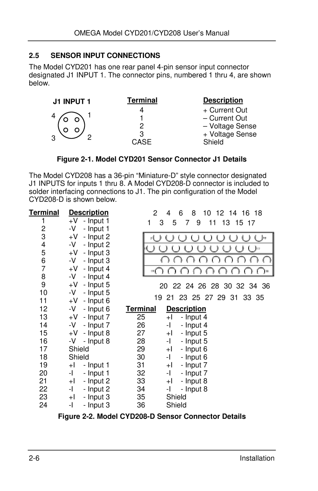
The Model CYD201 has one rear panel
J1 INPUT 1 | Terminal | Description | ||
4 | 1 | 4 | + Current Out | |
1 | – Current Out | |||
|
| |||
|
| 2 | – Voltage Sense | |
3 | 2 | 3 | + Voltage Sense | |
CASE | Shield | |||
|
| |||
Figure 2-1. Model CYD201 Sensor Connector J1 Details
The Model CYD208 has a
Terminal | Description | 2 | 4 6 | 8 | 10 12 14 16 18 |
1 | +V - Input 1 | 1 3 | 5 | 7 9 | 11 13 15 17 |
2
3+V - Input 2
4
5+V - Input 3
6
7+V - Input 4
8
9 | +V | - Input 5 | 20 | 22 24 26 28 30 32 34 36 | |||||||||
10 | - Input 5 | 19 | 21 | 23 | 25 | 27 | 29 | 31 | 33 | 35 | |||
11 | +V | - Input 6 | |||||||||||
Terminal | Description |
|
|
|
| ||||||||
12 | - Input 6 |
|
|
|
| ||||||||
13 | +V | - Input 7 | 25 | +I |
| - Input 4 |
|
|
|
| |||
14 | - Input 7 | 26 |
| - Input 4 |
|
|
|
| |||||
15 | +V | - Input 8 | 27 | +I |
| - Input 5 |
|
|
|
| |||
16 | - Input 8 | 28 |
| - Input 5 |
|
|
|
| |||||
17 | Shield | 29 | +I |
| - Input 6 |
|
|
|
| ||||
18 | Shield | 30 |
| - Input 6 |
|
|
|
| |||||
19 | +I | - Input 1 | 31 | +I |
| - Input 7 |
|
|
|
| |||
20 | - Input 1 | 32 |
| - Input 7 |
|
|
|
| |||||
21 | +I | - Input 2 | 33 | +I |
| - Input 8 |
|
|
|
| |||
22 | - Input 2 | 34 |
| - Input 8 |
|
|
|
| |||||
23 | +I | - Input 3 | 35 | Shield |
|
|
|
|
|
| |||
24 | - Input 3 | 36 | Shield |
|
|
|
|
|
| ||||
Figure 2-2. Model CYD208-D Sensor Connector Details
Installation |